background image

1. 

Standards and Safety Guidelines

The following sections describes the standard and safety guidelines for the product.

1.1 

Part Number Definition

PD-9501-5GCO/DC: 4–pairs DC input family.

Table 1-1. Part Number Definition

Symbol

Description

DC

Midspan has DC input.

1.2 

Electrical Compatibility Approvals

Microchip’s PD-9501-5GCO/DC series complies with the following standards:

• EN55035
• EN55032: Class B
• FCC Part 15: Class B
• VCCI

1.3 

Safety Standard Approvals

Microchip meets the following safety standards. Consult Microchip for a complete list of safety certifications.

• UL/IEC/EN62368-1
• UL/IEC/EN60950-22
• GS Compliance

1.4 

CE Marking

CE marking on this product indicates that this product complies with the Electromagnetic Compatibility (EMC)
Directive.

1.5 

GS Compliance

GS marking on this product indicates that the product complies with the German Product Safety Act.

1.6 

Surge/Lightening Protection

Microchip’s PD-9501-5GCO/DC is designed according to the following EMC requirements.

• ITU-T K.21 (6 kV enhanced surge) — Port and DC Main
• EN61000-4-5 (6 kV) — Port and DC Main
• GR-1089-CORE Issue 6 — Port Only

 PD-9501-5GCO/DC

Standards and Safety Guidelines

©

 2021 Microchip Technology Inc.

and its subsidiaries

 User Guide

DS00004336A-page 3

Summary of Contents for PD-9501-5GCO/DC

Page 1: ...minal The PD 9501 5GCO DC supports emerging wireless 5 Gbps devices such as wireless IEEE 802 11ac access points PoE Midspan powers devices that are PoE enabled or equipped to receive PoE These device...

Page 2: ...Model 6 3 1 Installation Overview 6 4 Troubleshooting 15 4 1 Preliminary Steps 15 4 2 Troubleshooting Steps 15 5 Specifications 16 5 1 Environmental Specifications 16 5 2 Electrical Specifications 16...

Page 3: ...icrochip for a complete list of safety certifications UL IEC EN62368 1 UL IEC EN60950 22 GS Compliance 1 4 CE Marking CE marking on this product indicates that this product complies with the Electroma...

Page 4: ...uipment and can pose a fire hazard If voltage indicated on the label is different from the power outlet voltage do not connect Midspan to this outlet All wiring and connections must comply with NFPA 7...

Page 5: ...endommager l quipement et constituer un risque d incendie Si le voltage indiqu sur l tiquette est diff rent du voltage de la source d alimentation ne pas connecter le Midspan cette prise Tous les c bl...

Page 6: ...e when connecting the DC power inlet terminals so that the ve and ve terminals are connected to the proper polarity 2 Ensure the DC power is within the allowed range 3 Earth ground screw must be conne...

Page 7: ...s no ON OFF switch simply plug the midspan into an DC power source PoE Midspan DC power lines should be connected to the socket outlet that shall be installed near the equipment and be easily accessib...

Page 8: ...ire stripper 1 Solid Wrench No 30 or Adjustable Wrench 3 1 3 Connect the Midspan to Ground Note Connect the midspan to ground only if replacing pre assembled ground cable 1 Connect the chassis bolt to...

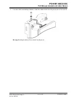
Page 9: ...are not provided with the kit 3 Tighten each screw until the midspan is attached safely to the mounting surface 3 1 5 Install the Midspan to a Pole Mount Adapter Before installing the midspan ensure...

Page 10: ...d to install the metal bracket on a pole with a diameter of 25 mm to 76 mm 1 in to 3 in b Pole of large diameter The following parts list identifies the components required to install the metal bracke...

Page 11: ...he chassis bolt to the earth ground point on the mount kit Warning Mounting bracket must be connected to earth ground PD 9501 5GCO DC PoE Midspan Installation Outdoor Model 2021 Microchip Technology I...

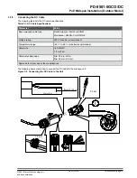
Page 12: ...ge 40 to 65 or better recommended Cable size 16 AWG 2C 1 5 mm2 2C Cable outer dimension Dia 3 16 in 3 8 in Dia 5 0 mm 9 5 mm Approved for indoor and outdoor applications The following figure shows how...

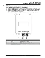
Page 13: ...washer and plug into the Data In port 3 Slide the washer and the upper cap towards the midspan and hand tighten the upper cap onto the Data In port 4 Repeat step 1 to step 3 to connect the RJ45 cable...

Page 14: ...llowing figure 3 Connect DC power lines from the Line In terminal item 1 in the following figure to main DC power Ensure that the power outlet is nearby and easily accessible Note Connect the midspan...

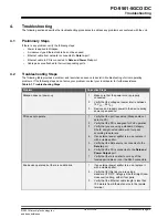
Page 15: ...4 VDC 3 Remove and reapply power to the device during power up sequence PD does not operate 1 Verify that the port is enabled Midspan did not detect a PD 2 Verify that the PD is designed for PoE opera...

Page 16: ...Input voltage 10 8 VDC 30 VDC Input current 8A maximum Available output power maximum 60W Nominal output voltage 54 VDC 5 3 Interface Table 5 3 Interface Parameter Type Input Data In Ethernet 10 100...

Page 17: ...consult the Microchip technical support team through the website or contact on the following number USA Canada Telephone 1 877 480 2323 Internet www microchip com support PD 9501 5GCO DC Contacting T...

Page 18: ...7 Revision History Revision Date Description A 12 2021 Initial Revision PD 9501 5GCO DC Revision History 2021 Microchip Technology Inc and its subsidiaries User Guide DS00004336A page 18...

Page 19: ...ncluded in this document Technical support is available through the website at www microchip com support Microchip Devices Code Protection Feature Note the following details of the code protection fea...

Page 20: ...ileSwitch APT ClockWorks The Embedded Control Solutions Company EtherSynch Flashtec Hyper Speed Control HyperLight Load IntelliMOS Libero motorBench mTouch Powermite 3 Precision Edge ProASIC ProASIC P...

Reviews: