background image

PIC16C62B/72A

DS35008C-page  114

Preliminary

 1998-2013 Microchip Technology Inc.

Instruction Set


.................................................................... 67

ADDLW


...................................................................... 69

ADDWF


...................................................................... 69

ANDLW


...................................................................... 69

ANDWF


...................................................................... 69

BCF


............................................................................ 69

BSF


............................................................................ 69

BTFSC


....................................................................... 70

BTFSS


....................................................................... 70

CALL


.......................................................................... 70

CLRF


......................................................................... 70

CLRW ......................................................................... 70
CLRWDT


................................................................... 70

COMF


........................................................................ 71

DECF


......................................................................... 71

DECFSZ


.................................................................... 71

GOTO


........................................................................ 71

INCF


.......................................................................... 71

INCFSZ


...................................................................... 71

IORLW


....................................................................... 72

IORWF


....................................................................... 72

MOVF


........................................................................ 72

MOVLW


..................................................................... 72

MOVWF


..................................................................... 72

NOP


........................................................................... 72

RETFIE


...................................................................... 73

RETLW


...................................................................... 73

RETURN


.................................................................... 73

RLF


............................................................................ 73

RRF


........................................................................... 73

SLEEP


....................................................................... 73

SUBLW


...................................................................... 74

SUBWF


...................................................................... 74

SWAPF


...................................................................... 74

XORLW


...................................................................... 74

XORWF


..................................................................... 74

Summary Table


......................................................... 68

INTCON Register


.......................................................... 9

13

GIE Bit


....................................................................... 13

INTE Bit


..................................................................... 13

INTF Bit


...................................................................... 13

PEIE Bit


..................................................................... 13

RBIE Bit


..................................................................... 13

RBIF Bit


.............................................................. 13

21

T0IE Bit


...................................................................... 13

T0IF Bit


...................................................................... 13

Interrupt Sources


........................................................ 55

62

A/D Conversion Complete


......................................... 51

Block Diagram


........................................................... 62

Capture Complete (CCP)


........................................... 34

Compare Complete (CCP)


......................................... 35

Interrupt on Change (RB7:RB4 )


............................... 21

RB0/INT Pin, External


........................................... 6

63

SSP Receive/Transmit Complete


.............................. 39

TMR0 Overflow


................................................... 26

63

TMR1 Overflow


................................................... 27

29

TMR2 to PR2 Match


.................................................. 32

TMR2 to PR2 Match (PWM)


............................... 31

36

Interrupts, Context Saving During


...................................... 63

Interrupts, Enable Bits

A/D Converter Enable (ADIE Bit)


............................... 14

CCP1 Enable (CCP1IE Bit)


....................................... 14

Global Interrupt Enable (GIE Bit)


........................ 13

62

Interrupt on Change (RB7:RB4) 
Enable (RBIE Bit)


................................................ 13

63

Peripheral Interrupt Enable (PEIE Bit)


....................... 13

RB0/INT Enable (INTE Bit)


........................................ 13

SSP Enable (SSPIE Bit)


............................................ 14

TMR0 Overflow Enable (T0IE Bit)


............................. 13

TMR1 Overflow Enable (TMR1IE Bit)


....................... 14

TMR2 to PR2 Match Enable (TMR2IE Bit)


................ 14

Interrupts, Flag Bits

A/D Converter Flag (ADIF Bit)


.............................15

51

CCP1 Flag (CCP1IF Bit)


.............................. 15

34

35

Interrupt on Change (RB7:RB4) 
Flag (RBIF Bit)


.............................................. 13

21

63

RB0/INT Flag (INTF Bit)


............................................ 13

SSP Flag (SSPIF Bit)


................................................ 15

TMR0 Overflow Flag (T0IF Bit)


...........................13

63

TMR1 Overflow Flag (TMR1IF Bit)


............................ 15

TMR2 to PR2 Match Flag (TMR2IF Bit)


.................... 15

K

KeeLoq

 Evaluation and Programming Tools


.................. 78

M

Master Clear (MCLR)


.......................................................... 6

MCLR Reset, Normal Operation


.................. 57

60

61

MCLR Reset, SLEEP


................................... 57

60

61

Memory Organization

Data Memory


............................................................... 8

Program Memory


......................................................... 7

MPLAB Integrated Development Environment Software


.. 75

O

OPCODE Field Descriptions


............................................. 67

OPTION_REG Register


..............................................10

12

INTEDG Bit


................................................................ 12

PS2:PS0 Bits


.......................................................12

25

PSA Bit


................................................................12

25

RBPU Bit


................................................................... 12

T0CS Bit


..............................................................12

25

T0SE Bit


..............................................................12

25

OSC1/CLKIN Pin


................................................................. 6

OSC2/CLKOUT Pin .............................................................. 6
Oscillator Configuration


...............................................55

56

HS


.......................................................................56

60

LP


........................................................................56

60

RC


.................................................................. 6

57

60

Selection (FOSC1:FOSC0 Bits).................................. 55
XT


........................................................................56

60

Oscillator, Timer1


........................................................27

29

Oscillator, WDT


................................................................. 64

P

Packaging


........................................................................ 105

Paging, Program Memory


.............................................7

17

PCON Register


............................................................16

60

BOR Bit


..................................................................... 16

POR Bit


..................................................................... 16

PICDEM-1 Low-Cost PIC MCU Demo Board


.................... 77

PICDEM-2 Low-Cost PIC16CXX Demo Board


................. 77

PICDEM-3 Low-Cost PIC16CXXX Demo Board


............... 77

PICSTART

 Plus Entry Level Development System


........ 77

PIE1 Register


..............................................................10

14

ADIE Bit


..................................................................... 14

CCP1IE Bit


................................................................ 14

SSPIE Bit


................................................................... 14

TMR1IE Bit


................................................................ 14

TMR2IE Bit


................................................................ 14

Pinout Descriptions

PIC16C62B/PIC16C72A


............................................. 6

Summary of Contents for PIC16C62B/72A

Page 1: ...ge 2 5V to 5 5V High Sink Source Current 25 25 mA Commercial Industrial and Extended temperature ranges Low power consumption 2 mA 5V 4 MHz 22 5 A typical 3V 32 kHz 1 A typical standby current Pin Dia...

Page 2: ...4 5 6 7 8 9 10 11 12 13 14 28 27 26 25 24 23 22 21 20 19 18 17 16 15 SDIP SOIC SSOP Windowed CERDIP Key Features PIC Mid Range Reference Manual DS33023 PIC16C62B PIC16C72A Operating Frequency DC 20 MH...

Page 3: ...f document DS30000 New Customer Notification System Register on our web site www microchip com cn to receive the most current information on our products Errata An errata sheet may exist for current d...

Page 4: ...PIC16C62B 72A DS35008C page 4 Preliminary 1998 2013 Microchip Technology Inc NOTES...

Page 5: ...plemented Figure 1 1 is the block diagram for both devices The pinouts are listed in Table 1 1 FIGURE 1 1 PIC16C62B PIC16C72A BLOCK DIAGRAM EPROM Program Memory 13 Data Bus 8 14 Program Bus Instructio...

Page 6: ...an also be the external interrupt pin RB1 22 22 I O TTL RB2 23 23 I O TTL RB3 24 24 I O TTL RB4 25 25 I O TTL Interrupt on change pin RB5 26 26 I O TTL Interrupt on change pin RB6 27 27 I O TTL ST 2 I...

Page 7: ...nce Manual DS33023 2 1 Program Memory Organization The PIC16C62B 72A devices have a 13 bit program counter capable of addressing an 8K x 14 program memory space Each device has 2K x 14 words of pro gr...

Page 8: ...can be accessed either directly or indi rectly through the File Select Register FSR Section 2 5 FIGURE 2 2 REGISTER FILE MAP RP1 1 RP0 STATUS 6 5 Note 1 Maintain this bit clear to ensure upward compa...

Page 9: ...T0IE INTE RBIE T0IF INTF RBIF 0000 000x 0000 000u 0Ch PIR1 ADIF 3 SSPIF CCP1IF TMR2IF TMR1IF 0 0000 0 0000 0Dh Unimplemented 0Eh TMR1L Holding register for the Least Significant Byte of the 16 bit TM...

Page 10: ...OR qq uu 8Fh 91h Unimplemented 92h PR2 Timer2 Period Register 1111 1111 1111 1111 93h SSPADD Synchronous Serial Port I2C mode Address Register 0000 0000 0000 0000 94h SSPSTAT SMP CKE D A P S R W UA BF...

Page 11: ...respectively in sub traction See the SUBLW and SUBWF instructions R W 0 R W 0 R W 0 R 1 R 1 R W x R W x R W x IRP RP1 RP0 TO PD Z DC C R Readable bit W Writable bit U Unimplemented bit read as 0 n Val...

Page 12: ...it n Value at POR reset bit7 bit0 bit 7 RBPU PORTB Pull up Enable bit 1 PORTB pull ups are disabled 0 PORTB pull ups are enabled for all PORTB inputs bit 6 INTEDG Interrupt Edge Select bit 1 Interrupt...

Page 13: ...un masked interrupts 0 Disables all interrupts bit 6 PEIE Peripheral Interrupt Enable bit 1 Enables all un masked peripheral interrupts 0 Disables all peripheral interrupts bit 5 T0IE TMR0 Overflow In...

Page 14: ...Interrupt Enable bit 1 Enables the A D interrupt 0 Disables the A D interrupt bit 5 4 Unimplemented Read as 0 bit 3 SSPIE Synchronous Serial Port Interrupt Enable bit 1 Enables the SSP interrupt 0 Di...

Page 15: ...ed must be cleared in software 0 The A D conversion is not complete bit 5 4 Unimplemented Read as 0 bit 3 SSPIF Synchronous Serial Port Interrupt Flag bit 1 The transmission reception is complete must...

Page 16: ...et the BOR bit on a POR and check it on subsequent resets If BOR is cleared while POR remains set a Brown out reset has occurred If the BODEN bit is clear the BOR bit may be ignored U 0 U 0 U 0 U 0 U...

Page 17: ...r is not accessible The PC is PUSHed onto the stack when a CALL instruction is executed or an interrupt causes a branch The stack is POPed in the event of a RETURN RETLW or a RET FIE instruction execu...

Page 18: ...OW TO CLEAR RAM USING INDIRECT ADDRESSING movlw 0x20 initialize pointer movwf FSR to RAM NEXT clrf INDF clear INDF register incf FSR inc pointer btfss FSR 4 all done goto NEXT NO clear next CONTINUE Y...

Page 19: ...4 T0CKI pin The RA4 T0CKI pin is a Schmitt Trigger input and an open drain output All other RA port pins have TTL input levels and full CMOS output drivers Pin RA5 is multiplexed with the SSP to becom...

Page 20: ...Input output or slave select input for synchronous serial port or analog input 1 Legend TTL TTL input ST Schmitt Trigger input Note 1 The PIC16C62B does not implement the A D module Address Name Bit 7...

Page 21: ...device from SLEEP The user in the interrupt service routine can clear the inter rupt in the following manner a Any read or write of PORTB This will end the mismatch condition b Clear flag bit RBIF A...

Page 22: ...ernal software programmable weak pull up RB6 bit6 TTL ST 2 Input output pin with interrupt on change Internal software programmable weak pull up Serial programming clock RB7 bit7 TTL ST 2 Input output...

Page 23: ...in Some peripherals override the TRIS bit to make a pin an out put while other peripherals override the TRIS bit to make a pin an input Since the TRIS bit override maybe in effect while the peripheral...

Page 24: ...ut PWM1 output No RC3 SCK SCL bit3 ST RC3 can also be the synchronous serial clock for both SPI and I2C modes No RC4 SDI SDA bit4 ST RC4 can also be the SPI Data In SPI mode or data I O I2 C mode No R...

Page 25: ...trical Specifications section of this manual and in the PIC MCU Mid Range Refer ence Manual DS33023 4 2 Prescaler An 8 bit counter is available as a prescaler for the Timer0 module or as a postscaler...

Page 26: ...ESET a specific instruction sequence shown in the PIC MCU Mid Range Reference Manual DS33023 must be executed when chang ing the prescaler assignment from Timer0 to the WDT This sequence must be fol l...

Page 27: ...RC0 T1OSO T1CKI pins become inputs That is the TRISC 1 0 value is ignored Timer1 also has an internal reset input This reset can be generated by the CCP module as a special event trigger Section 7 0 R...

Page 28: ...T1CKPS1 T1CKPS0 SLEEP input T1OSCEN Enable Oscillator 1 FOSC 4 Internal Clock TMR1ON on off Prescaler 1 2 4 8 Synchronize det 1 0 0 1 Synchronized clock input 2 RC0 T1OSO T1CKI RC1 T1OSI Note 1 When...

Page 29: ...onous counter mode this reset operation may not work In the event that a write to Timer1 coincides with a spe cial event trigger from CCP1 the write will take prece dence In this mode of operation the...

Page 30: ...PIC16C62B 72A DS35008C page 30 Preliminary 1998 2013 Microchip Technology Inc NOTES...

Page 31: ...Mid Range Reference Manual DS33023 FIGURE 6 1 TIMER2 BLOCK DIAGRAM REGISTER 6 1 T2CON TIMER2 CONTROL REGISTER ADDRESS 12h Comparator TMR2 Sets flag TMR2 reg output 1 Reset Postscaler Prescaler PR2 re...

Page 32: ...errupt The Timer2 module has an 8 bit period register PR2 Timer2 increments from 00h until it matches PR2 and then resets to 00h on the next increment cycle PR2 is a readable and writable register The...

Page 33: ...1 Compare Compare The compare s should be configured for the special event trigger which clears TMR1 PWM PWM The PWMs will have the same frequency and update rate TMR2 interrupt PWM Capture None PWM C...

Page 34: ...false capture interrupt may be generated The user should clear CCP1IE PIE1 2 before changing the capture mode to avoid false interrupts Clear the interrupt flag bit CCP1IE before setting CCP1IE 7 1 4...

Page 35: ...air and starts an A D conversion if the A D module is enabled TABLE 7 3 REGISTERS ASSOCIATED WITH CAPTURE COMPARE AND TIMER1 CCPR1H CCPR1L TMR1H TMR1L Comparator Q S R Output Logic Special Event Trigg...

Page 36: ...by CCPR1L CCP1CON 5 4 The following equation is used to calculate the PWM duty cycle in time PWM on time CCPR1L CCP1CON 5 4 Tosc TMR2 prescale value CCPR1L and CCP1CON 5 4 can be written to at any tim...

Page 37: ...2 Value 0xFF 0xFF 0xFF 0x3F 0x1F 0x17 Maximum Resolution bits 10 10 10 8 7 5 5 Address Name Bit 7 Bit 6 Bit 5 Bit 4 Bit 3 Bit 2 Bit 1 Bit 0 Value on POR BOR Value on all other resets 0Bh 8Bh INTCON GI...

Page 38: ...PIC16C62B 72A DS35008C page 38 Preliminary 1998 2013 Microchip Technology Inc NOTES...

Page 39: ...Slave Select SS RA5 SS AN4 When initializing the SPI several options need to be specified This is done by programming the appropriate control bits in the SSPCON register SSPCON 5 0 and SSPSTAT 7 6 Th...

Page 40: ...P1IF TMR2IF TMR1IF 0 0000 0 0000 8Ch PIE1 ADIE SSPIE CCP1IE TMR2IE TMR1IE 0 0000 0 0000 13h SSPBUF Synchronous Serial Port Receive Buffer Transmit Register xxxx xxxx uuuu uuuu 14h SSPCON WCOL SSPOV SS...

Page 41: ...ns to be operated as open drain outputs provided these pins are programmed to inputs by setting the appropriate TRISC bits Additional information on SSP I2 C operation may be found in the PIC MCU Mid...

Page 42: ...ll receive the second address byte For a 10 bit address the first byte would equal 1111 0 A9 A8 0 where A9 and A8 are the two MSbs of the address The sequence of events for 10 bit address is as follow...

Page 43: ...OV SSPCON 6 is set An SSP interrupt is generated for each data transfer byte Flag bit SSPIF PIR1 3 must be cleared in soft ware The SSPSTAT register is used to determine the status of the byte FIGURE...

Page 44: ...erated for each data transfer byte Flag bit SSPIF must be cleared in software and the SSPSTAT register used to determine the status of the byte Flag bit SSPIF is set on the falling edge of the ninth c...

Page 45: ...he I2 C bus may be taken when bit P SSPSTAT 4 is set or the bus is idle and both the S and P bits clear When the bus is busy enabling the SSP Interrupt will generate the interrupt when the STOP condit...

Page 46: ...ast byte received or transmitted was address bit 4 P Stop bit I2C mode only This bit is cleared when the SSP module is disabled or when the Start bit is detected last SSPEN is cleared 1 Indicates that...

Page 47: ...either mode 0 No overflow bit 5 SSPEN Synchronous Serial Port Enable bit In SPI mode 1 Enables serial port and configures SCK SDO and SDI as serial port pins 0 Disables serial port and configures thes...

Page 48: ...PIC16C62B 72A DS35008C page 48 Preliminary 1998 2013 Microchip Technology Inc NOTES...

Page 49: ...state This forces the A D module to be turned off and any conversion is aborted The ADCON0 register shown in Figure 9 1 controls the operation of the A D module The ADCON1 regis ter shown in Figure 9...

Page 50: ...Readable bit W Writable bit U Unimplemented bit read as 0 n Value at POR reset bit7 bit0 bit 7 3 Unimplemented Read as 0 bit 2 0 PCFG2 PCFG0 A D Port Configuration Control bits A Analog input D Digita...

Page 51: ...following steps should be fol lowed for doing an A D conversion 1 Configure the A D module Configure analog pins voltage reference and digital I O ADCON1 Select A D input channel ADCON0 Select A D co...

Page 52: ...TACQ see Equation 9 1 This equation calculates the acquisition time to within 1 2 LSb error 512 steps for the A D The 1 2 LSb error is the maximum error allowed for the A D to meet its specified accu...

Page 53: ...dependent of the state of the CHS2 CHS0 bits and the TRIS bits TABLE 9 1 TAD vs DEVICE OPERATING FREQUENCIES Note 1 When reading the port register all pins configured as analog input channels will rea...

Page 54: ...on If the A D module is not enabled ADON is cleared then the special event trigger will be ignored by the A D module but will still reset the Timer1 counter TABLE 9 2 SUMMARY OF A D REGISTERS Note The...

Page 55: ...the application The RC oscillator option saves system cost while the LP crystal option saves power A set of configuration bits are used to select various options Additional information on special feat...

Page 56: ...2 Open Clock from ext system PIC16CXXX Ranges Tested Mode Freq OSC1 OSC2 XT 455 kHz 2 0 MHz 4 0 MHz 68 100 pF 15 68 pF 15 68 pF 68 100 pF 15 68 pF 15 68 pF HS 8 0 MHz 16 0 MHz 10 68 pF 10 22 pF 10 68...

Page 57: ...uring SLEEP WDT Reset during normal operation WDT Wake up during SLEEP Brown out Reset BOR Some registers are not affected in any reset condition their status is unknown on POR and unchanged by any ot...

Page 58: ...ESET CIRCUIT S R Q External Reset MCLR VDD OSC1 WDT Module VDD rise detect OST PWRT On chip RC OSC WDT Time out Power on Reset OST 10 bit Ripple counter PWRT Chip_Reset 10 bit Ripple counter Reset Ena...

Page 59: ...rt up Timer OST provides a delay of 1024 oscillator cycles from OSC1 input after the PWRT delay is over TOST parameter 32 This ensures that the crystal oscillator or resonator has started and stabiliz...

Page 60: ...wn out has occurred POR Power on Reset Status bit is cleared on a Power on Reset and unaffected otherwise The user Status Register PCON Register TABLE 10 3 TIME OUT IN VARIOUS SITUATIONS TABLE 10 4 ST...

Page 61: ...2B 72A xxxx xxxx uuuu uuuu uuuu uuuu SSPCON 62B 72A 0000 0000 0000 0000 uuuu uuuu CCPR1L 62B 72A xxxx xxxx uuuu uuuu uuuu uuuu CCPR1H 62B 72A xxxx xxxx uuuu uuuu uuuu uuuu CCP1CON 62B 72A 00 0000 00 0...

Page 62: ...ed in special function registers PIE1 and PIE2 and the peripheral interrupt enable bit is contained in special function reg ister INTCON When an interrupt is responded to the GIE bit is cleared to dis...

Page 63: ...ng clearing enable bit RBIE INTCON 4 Section 3 2 10 11 Context Saving During Interrupts During an interrupt only the return PC value is saved on the stack Typically users may wish to save key reg iste...

Page 64: ...ameter 31 is multiplied by the prescaler ratio when the prescaler is assigned to the WDT The prescaler assignment assigned to either the WDT or Timer0 and prescaler ratio are set in the OPTION_REG reg...

Page 65: ...an external clock CCP1 is in com pare mode 4 SSP Start Stop bit detect interrupt 5 SSP transmit or receive in slave mode SPI I2C 6 USART RX or TX synchronous slave mode Other peripherals cannot genera...

Page 66: ...mming volt age This allows customers to manufacture boards with unprogrammed devices and then program the micro controller just before shipping the product This also allows the most recent firmware or...

Page 67: ...uction cycles with the second cycle executed as a NOP One instruc tion cycle consists of four oscillator periods Thus for an oscillator frequency of 4 MHz the normal instruction execution time is 1 s...

Page 68: ...r f Bit Set f Bit Test f Skip if Clear Bit Test f Skip if Set 1 1 1 2 1 2 01 01 01 01 00bb 01bb 10bb 11bb bfff bfff bfff bfff ffff ffff ffff ffff 1 2 1 2 3 3 LITERAL AND CONTROL OPERATIONS ADDLW ANDLW...

Page 69: ...s stored back in register f ANDLW AND Literal with W Syntax label ANDLW k Operands 0 k 255 Operation W AND k W Status Affected Z Description The contents of W register are AND ed with the eight bit li...

Page 70: ...truction CALL Call Subroutine Syntax label CALL k Operands 0 k 2047 Operation PC 1 TOS k PC 10 0 PCLATH 4 3 PC 12 11 Status Affected None Description Call Subroutine First return address PC 1 is pushe...

Page 71: ...struction is executed If the result is 0 then a NOP is executed instead making it a 2TCY instruction GOTO Unconditional Branch Syntax label GOTO k Operands 0 k 2047 Operation k PC 10 0 PCLATH 4 3 PC 1...

Page 72: ...Syntax label MOVF f d Operands 0 f 127 d 0 1 Operation f destination Status Affected Z Description The contents of register f is moved to a destination dependant upon the sta tus of d If d 0 destinat...

Page 73: ...label RLF f d Operands 0 f 127 d 0 1 Operation See description below Status Affected C Description The contents of register f are rotated one bit to the left through the Carry Flag If d is 0 the resul...

Page 74: ...ibbles in f Syntax label SWAPF f d Operands 0 f 127 d 0 1 Operation f 3 0 destination 7 4 f 7 4 destination 3 0 Status Affected None Description The upper and lower nibbles of regis ter f are exchange...

Page 75: ...y to easily switch from the cost effective simulator to the full featured emulator with minimal retraining 12 2 MPASM Assembler MPASM is a full featured universal macro assembler for all PIC MCUs It c...

Page 76: ...t are generally found on more expensive devel opment tools The PC platform and Microsoft Windows 3 x 95 98 environment were chosen to best make these features available to you the end user MPLAB ICE 2...

Page 77: ...to PORTB 12 14 PICDEM 2 Low Cost PIC16CXX Demonstration Board The PICDEM 2 is a simple demonstration board that supports the PIC16C62 PIC16C64 PIC16C65 PIC16C73 and PIC16C74 microcontrollers All the...

Page 78: ...gner s Kit supports all Microchip 2 wire and 3 wire Serial EEPROMs The kit includes everything necessary to read write erase or program special features of any Microchip SEEPROM product including Smar...

Page 79: ...CD In Circuit Debugger Programmers PICSTART Plus Low Cost Universal Dev Kit PRO MATE II Universal Programmer Demo Boards and Eval Kits SIMICE PICDEM 1 PICDEM 2 PICDEM 3 PICDEM 14A PICDEM 17 K EE L OQ...

Page 80: ...PIC16C62B 72A DS35008C page 80 Preliminary 1998 2013 Microchip Technology Inc NOTES...

Page 81: ...any I O pin 25 mA Maximum current sunk by PORTA and PORTB combined 200 mA Maximum current sourced by PORTA and PORTB combined 200 mA Maximum current sunk by PORTC 200 mA Maximum current sourced by PO...

Page 82: ...A JW VOLTAGE FREQUENCY GRAPH Frequency Voltage 6 0 V 5 5 V 4 5 V 4 0 V 2 0 V 20 MHz 5 0 V 3 5 V 3 0 V 2 5 V PIC16CXXX PIC16CXXX 20 Frequency Voltage 6 0 V 5 5 V 4 5 V 4 0 V 2 0 V 10 MHz 5 0 V 3 5 V 3...

Page 83: ...Microchip Technology Inc Preliminary DS35008C page 83 PIC16C62B 72A FIGURE 13 3 PIC16C62B 72A 04 VOLTAGE FREQUENCY GRAPH Frequency Voltage 6 0 V 5 5 V 4 5 V 4 0 V 2 0 V 5 0 V 3 5 V 3 0 V 2 5 V PIC16CX...

Page 84: ...rown out Reset 6 0 TBD 20 200 A A WDTE BIT SET VDD 4 0V BODEN bit set VDD 5 0V These parameters are characterized but not tested Data in Typ column is at 5V 25 C unless otherwise stated These paramete...

Page 85: ...et VDD 5 0V These parameters are characterized but not tested Data in Typ column is at 5V 25 C unless otherwise stated These parameters are for design guidance only and are not tested Note 1 This is t...

Page 86: ...entire VDD range D041 with Schmitt Trigger buffer 0 8VDD VDD V For entire VDD range D042 MCLR 0 8VDD VDD V D042A OSC1 XT HS and LP modes 0 7VDD VDD V Note1 D043 OSC1 in RC mode 0 9VDD Vdd V Input Lea...

Page 87: ...400 pF DC CHARACTERISTICS Standard Operating Conditions unless otherwise stated Operating temperature 0 C TA 70 C for commercial 40 C TA 85 C for industrial 40 C TA 125 C for extended Operating voltag...

Page 88: ...tions only T F Frequency T Time Lowercase letters pp and their meanings pp cc CCP1 osc OSC1 ck CLKOUT rd RD cs CS rw RD or WR di SDI sc SCK do SDO ss SS dt Data in t0 T0CKI io I O port t1 T1CKI mc MCL...

Page 89: ...CIFICATIONS AC FIGURE 13 4 LOAD CONDITIONS FOR DEVICE TIMING SPECIFICATIONS AC CHARACTERISTICS Standard Operating Conditions unless otherwise stated Operating temperature 0 C TA 70 C for commercial 40...

Page 90: ...4 FOSC 3 TosL TosH External Clock in OSC1 High or Low Time 100 ns XT oscillator 2 5 s LP oscillator 15 ns HS oscillator 4 TosR TosF External Clock in OSC1 Rise or Fall Time 25 ns XT oscillator 50 ns...

Page 91: ...ort input invalid I O in hold time PIC16CXX 100 ns 18A PIC16LCXX 200 ns 19 TioV2osH Port input valid to OSC1 I O in setup time 0 ns 20 TioR Port output rise time PIC16CXX 10 40 ns 20A PIC16LCXX 80 ns...

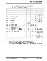
Page 92: ...ut Period No Prescaler 7 18 33 ms VDD 5V 40 C to 125 C 32 Tost Oscillator Start up Timer Period 1024 TOSC TOSC OSC1 period 33 Tpwrt Power up Timer Period 28 72 132 ms VDD 5V 40 C to 125 C 34 TIOZ I O...

Page 93: ...PIC16LCXX 25 ns Asynchronous PIC16CXX 30 ns PIC16LCXX 50 ns 46 Tt1L T1CKI Low Time Synchronous Prescaler 1 0 5TCY 20 ns Must also meet parameter 47 Synchronous Prescaler 2 4 8 PIC16CXX 15 ns PIC16LCX...

Page 94: ...No Prescaler 0 5TCY 20 ns With Prescaler PIC16CXX 10 ns PIC16LCXX 20 ns 52 TccP CCP1 input period 3TCY 40 N ns N prescale value 1 4 or 16 53 TccR CCP1 output rise time PIC16CXX 10 25 ns PIC16LCXX 25...

Page 95: ...st clock edge of Byte2 1 5TCY 40 ns Note 1 74 TscH2diL TscL2diL Hold time of SDI data input to SCK edge 100 ns 75 TdoR SDO data output rise time PIC16CXX 10 25 ns PIC16LCXX 20 45 ns 76 TdoF SDO data o...

Page 96: ...TscL2diL Hold time of SDI data input to SCK edge 100 ns 75 TdoR SDO data output rise time PIC16CXX 10 25 ns PIC16LCXX 20 45 ns 76 TdoF SDO data output fall time 10 25 ns 78 TscR SCK output rise time...

Page 97: ...TscL2diL Hold time of SDI data input to SCK edge 100 ns 75 TdoR SDO data output rise time PIC16CXX 10 25 ns PIC16LCXX 20 45 ns 76 TdoF SDO data output fall time 10 25 ns 77 TssH2doZ SS to SDO output...

Page 98: ...output rise time PIC16CXX 10 25 ns PIC16LCXX 20 45 ns 76 TdoF SDO data output fall time 10 25 ns 77 TssH2doZ SS to SDO output hi impedance 10 50 ns 78 TscR SCK output rise time master mode PIC16CXX 10...

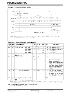
Page 99: ...relevant for repeated START condition Setup time 400 kHz mode 600 91 THD STA START condition 100 kHz mode 4000 ns After this period the first clock pulse is generated Hold time 400 kHz mode 600 92 TSU...

Page 100: ...mode 0 ns 400 kHz mode 0 0 9 s 107 TSU DAT Data input setup time 100 kHz mode 250 ns Note 2 400 kHz mode 100 ns 92 TSU STO STOP condition setup time 100 kHz mode 4 7 s 400 kHz mode 0 6 s 109 TAA Outpu...

Page 101: ...voltage 2 5V VDD 0 3 V A25 VAIN Analog input voltage VSS 0 3 VREF 0 3 V A30 ZAIN Recommended impedance of analog voltage source 10 0 k A40 IAD A D conversion current VDD PIC16CXX 180 A Average current...

Page 102: ...om the last sam pled voltage as stated on CHOLD 134 TGO Q4 to A D clock start TOSC 2 If the A D clock source is selected as RC a time of TCY is added before the A D clock starts This allows the SLEEP...

Page 103: ...operate properly only within the specified range The data presented in this section is a statistical summary of data collected on units from different lots over a period of time and matrix samples Ty...

Page 104: ...PIC16C62B 72A DS35008C page 104 Preliminary 1998 2013 Microchip Technology Inc NOTES...

Page 105: ...on AA Year code last 2 digits of calendar year BB Week code week of January 1 is week 01 C Facility code of the plant at which wafer is manufactured O Outside Vendor C 5 Line S 6 Line H 8 Line D Mask...

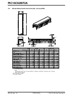
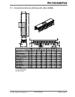
Page 106: ...g Plane 35 18 34 67 34 16 1 385 1 365 1 345 D Overall Length 8 51 7 80 7 09 335 307 279 E1 Molded Package Width 8 26 7 94 7 62 325 313 300 E Shoulder to Shoulder Width 0 38 015 A1 Base to Seating Plan...

Page 107: ...012 010 008 c Lead Thickness 3 68 3 56 3 43 145 140 135 L Tip to Seating Plane 37 72 37 02 36 32 1 485 1 458 1 430 D Overall Length 7 49 7 37 7 24 295 290 285 E1 Ceramic Pkg Width 8 26 7 94 7 62 325 3...

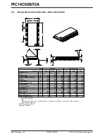
Page 108: ...8 17 87 17 65 712 704 695 D Overall Length 7 59 7 49 7 32 299 295 288 E1 Molded Package Width 10 67 10 34 10 01 420 407 394 E Overall Width 0 30 0 20 0 10 012 008 004 A1 Standoff 2 39 2 31 2 24 094 09...

Page 109: ...old Draft Angle Top 0 38 0 32 0 25 015 013 010 B Lead Width 203 20 101 60 0 00 8 4 0 Foot Angle 0 25 0 18 0 10 010 007 004 c Lead Thickness 0 94 0 75 0 56 037 030 022 L Foot Length 10 34 10 20 10 06 4...

Page 110: ...PIC16C62B 72A DS35008C page 110 Preliminary 1998 2013 Microchip Technology Inc NOTES...

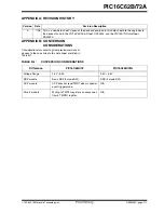
Page 111: ...n A 7 98 This is a new data sheet However the devices described in this data sheet are the upgrades to the devices found in the PIC16C6X Data Sheet DS30234 and the PIC16C7X Data Sheet DS30390 TABLE B...

Page 112: ...P through interrupt is added 11 Two separate timers Oscillator Start up Timer OST and Power up Timer PWRT are included for more reliable power up These tim ers are invoked selectively to avoid unneces...

Page 113: ...Two CCP Modules 33 Capture Compare PWM CCP 33 CCP1CON Register 9 33 CCPR1H Register 9 33 CCPR1L Register 9 33 Enable CCP1IE Bit 14 Flag CCP1IF Bit 15 RC2 CCP1 Pin 6 Timer Resources 33 Timing Diagram 9...

Page 114: ...0 Overflow Enable T0IE Bit 13 TMR1 Overflow Enable TMR1IE Bit 14 TMR2 to PR2 Match Enable TMR2IE Bit 14 Interrupts Flag Bits A D Converter Flag ADIF Bit 15 51 CCP1 Flag CCP1IF Bit 15 34 35 Interrupt o...

Page 115: ...ock Diagram 26 Rate Select PS2 PS0 Bits 12 25 Switching Between Timer0 and WDT 26 Prescaler Timer1 28 Select T1CKPS1 T1CKPS0 Bits 27 Prescaler Timer2 36 Select T2CKPS1 T2CKPS0 Bits 31 PRO MATE II Univ...

Page 116: ...am 28 Capacitor Selection 29 Clock Source Select TMR1CS Bit 27 External Clock Input Sync T1SYNC Bit 27 Module On Off TMR1ON Bit 27 Oscillator 27 29 Oscillator Enable T1OSCEN Bit 27 Overflow Enable TMR...

Page 117: ...ip sales offices distributors and factory representatives CUSTOMER CHANGE NOTIFICATION SERVICE Microchip s customer notification service helps keep customers current on Microchip products Subscribers...

Page 118: ...s Manager RE Reader Response Total Pages Sent ________ From Name Company Address City State ZIP Country Telephone _______ _________ _________ Application optional Would you like a reply Y N Device Lit...

Page 119: ...l Microchip sales office 2 The Microchip Corporate Literature Center U S FAX 480 786 7277 3 The Microchip Worldwide Site www microchip com Please specify which device revision of silicon and Data Shee...

Page 120: ...PIC16C62B 72A DS35008C page 120 Preliminary 1913 Microchip Technology Inc...

Page 121: ...gy Incorporated in the U S A GestIC and ULPP are registered trademarks of Microchip Technology Germany II GmbH Co KG a subsidiary of Microchip Technology Inc in other countries All other trademarks me...

Page 122: ...l 86 21 5407 5533 Fax 86 21 5407 5066 China Shenyang Tel 86 24 2334 2829 Fax 86 24 2334 2393 China Shenzhen Tel 86 755 8864 2200 Fax 86 755 8203 1760 China Wuhan Tel 86 27 5980 5300 Fax 86 27 5980 511...

Page 123: ...L PIC16LC62B 04I SP PIC16LC62B 04I SS PIC16LC62B 04I SO PIC16LC62B 04 SO PIC16LC62B 04 SP PIC16LC62B 04 SS PIC16LC62BT 04I SS PIC16LC62BT 04I SO PIC16LC72AT 04 SS PIC16LC72AT 04 SO PIC16LC62BT 04I ML...

Reviews: