2003 Microchip Technology Inc.
DS39582B-page 113
PIC16F87XA
10.1
USART Baud Rate Generator
(BRG)
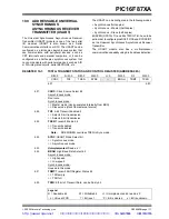
The BRG supports both the Asynchronous and Syn-
chronous modes of the USART. It is a dedicated 8-bit
baud rate generator. The SPBRG register controls the
period of a free running 8-bit timer. In Asynchronous
mode, bit BRGH (TXSTA<2>) also controls the baud
rate. In Synchronous mode, bit BRGH is ignored.
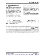
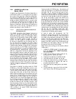
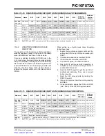
Table 10-1 shows the formula for computation of the
baud rate for different USART modes which only apply
in Master mode (internal clock).
Given the desired baud rate and F
OSC
, the nearest
integer value for the SPBRG register can be calculated
using the formula in Table 10-1. From this, the error in
baud rate can be determined.
It may be advantageous to use the high baud rate
(BRGH =
1
) even for slower baud clocks. This is
because the F
OSC
/(16 (X + 1)) equation can reduce the
baud rate error in some cases.
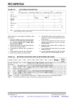
Writing a new value to the SPBRG register causes the
BRG timer to be reset (or cleared). This ensures the
BRG does not wait for a timer overflow before
outputting the new baud rate.
10.1.1
SAMPLING
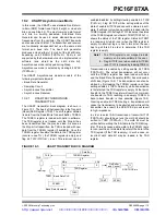
The data on the RC7/RX/DT pin is sampled three times
by a majority detect circuit to determine if a high or a
low level is present at the RX pin.
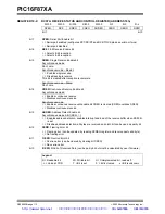
TABLE 10-1:
BAUD RATE FORMULA
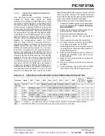
TABLE 10-2:
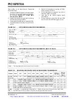
REGISTERS ASSOCIATED WITH BAUD RATE GENERATOR
SYNC
BRGH =
0
(Low Speed)
BRGH =
1
(High Speed)
0
1
(Asynchronous) Baud Rate = F
OSC
/(64 (X + 1))
(Synchronous) Baud Rate = F
OSC
/(4 (X + 1))
Baud Rate = F
OSC
/(16 (X + 1))
N/A
Legend: X = value in SPBRG (0 to 255)
Address
Name
Bit 7
Bit 6
Bit 5
Bit 4
Bit 3
Bit 2
Bit 1
Bit 0
Value on:
POR, BOR
Value on
all other
Resets
98h
TXSTA
CSRC
TX9
TXEN
SYNC
—
BRGH
TRMT
TX9D
0000 -010 0000 -010
18h
RCSTA
SPEN
RX9
SREN
CREN
ADDEN
FERR
OERR RX9D
0000 000x 0000 000x
99h
SPBRG
Baud Rate Generator Register
0000 0000 0000 0000
Legend:
x
= unknown,
-
= unimplemented, read as ‘
0
’. Shaded cells are not used by the BRG.
http://www.xinpian.net
提供单片机解密、IC解密、芯片解密业务
010-62245566 13810019655

