2003 Microchip Technology Inc.
DS39582B-page 49
PIC16F87XA
4.5
PORTE and TRISE Register
PORTE has three pins (RE0/RD/AN5, RE1/WR/AN6
and RE2/CS/AN7) which are individually configurable
as inputs or outputs. These pins have Schmitt Trigger
input buffers.
The PORTE pins become the I/O control inputs for the
microprocessor port when bit PSPMODE (TRISE<4>) is
set. In this mode, the user must make certain that the
TRISE<2:0> bits are set and that the pins are configured
as digital inputs. Also, ensure that ADCON1 is config-
ured for digital I/O. In this mode, the input buffers are
TTL.
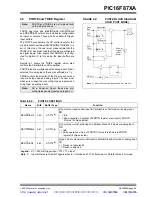
Register 4-1 shows the TRISE register which also
controls the Parallel Slave Port operation.
PORTE pins are multiplexed with analog inputs. When
selected for analog input, these pins will read as ‘
0
’s.
TRISE controls the direction of the RE pins, even when
they are being used as analog inputs. The user must
make sure to keep the pins configured as inputs when
using them as analog inputs.
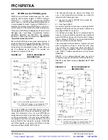
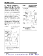
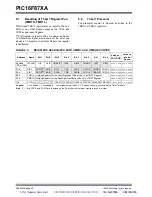
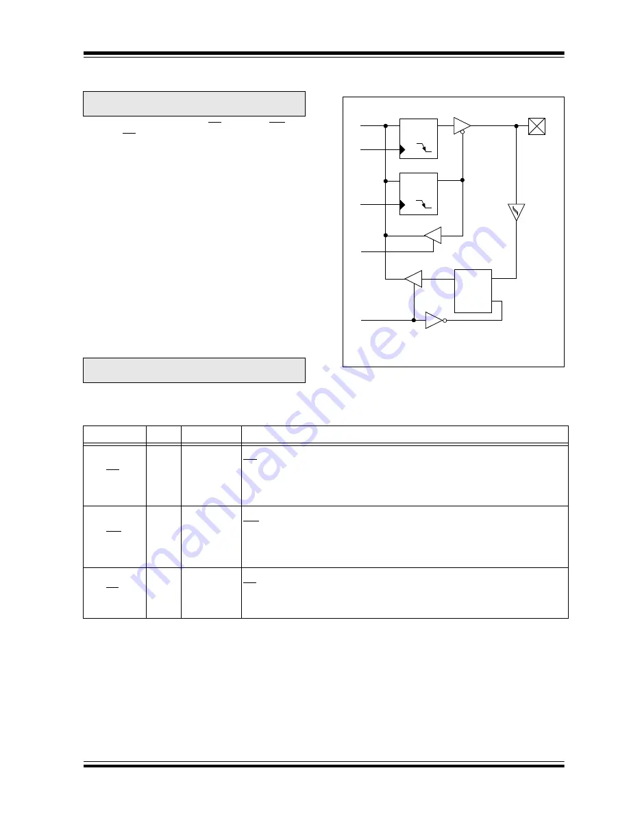
FIGURE 4-9:
PORTE BLOCK DIAGRAM
(IN I/O PORT MODE)
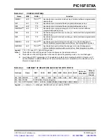
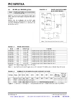
TABLE 4-9:
PORTE FUNCTIONS
Note:
PORTE and TRISE are not implemented
on the 28-pin devices.
Note:
On a Power-on Reset, these pins are
configured as analog inputs and read as ‘
0
’.
Data
Bus
WR
Port
WR
TRIS
RD Port
Data Latch
TRIS Latch
RD
Schmitt
Trigger
Input
Buffer
Q
D
CK
Q
D
CK
EN
Q
D
EN
I/O pin
(1)
Note 1: I/O pins have protection diodes to V
DD
and V
SS
.
TRIS
Name
Bit#
Buffer Type
Function
RE0/RD/AN5
bit 0
ST/TTL
(1)
I/O port pin or read control input in Parallel Slave Port mode or analog input:
RD
1
= Idle
0
= Read operation. Contents of PORTD register are output to PORTD
I/O pins (if chip selected).
RE1/WR/AN6
bit 1
ST/TTL
(1)
I/O port pin or write control input in Parallel Slave Port mode or analog input:
WR
1
= Idle
0
= Write operation. Value of PORTD I/O pins is latched into PORTD
register (if chip selected).
RE2/CS/AN7
bit 2
ST/TTL
(1)
I/O port pin or chip select control input in Parallel Slave Port mode or analog input:
CS
1
= Device is not selected
0
= Device is selected
Legend: ST = Schmitt Trigger input, TTL = TTL input
Note 1:
Input buffers are Schmitt Triggers when in I/O mode and TTL buffers when in Parallel Slave Port mode.
http://www.xinpian.net
提供单片机解密、IC解密、芯片解密业务
010-62245566 13810019655

