PIC24FV16KM204 FAMILY
DS33030A-page 144
Advance Information
2013 Microchip Technology Inc.
13.1
Time Base Generator
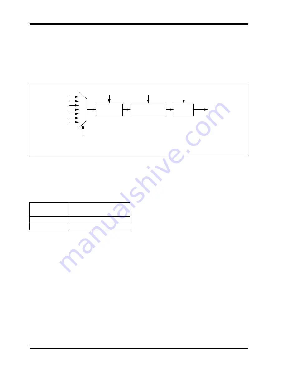
The Timer Clock Generator (TCG) generates a clock
for the module’s internal time base, using one of the
clock signals already available on the microcontroller.
This is used as the time reference for the module in its
three major modes. The internal time base is shown in
.
There are eight inputs available to the clock generator,
which are selected using the CLKSEL<2:0> bits
(CCPxCON1L<10:8>). The system clock is the default
source (CLKSEL<2:0> =
000
). When other clock
sources are selected, clock input timing restrictions or
module operating restrictions may exist.
FIGURE 13-2:
TIMER CLOCK GENERATOR
13.2
General Purpose Timer
Timer mode is selected when CCSEL =
0
and
MOD<3:0> =
0000
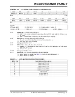
. The timer can function as a 32-bit
timer or a dual 16-bit timer, depending on the setting of
the T32 bit (
).
TABLE 13-1:
TIMER OPERATION MODE
Dual 16-Bit Timer mode provides a simple timer func-
tion with two independent 16-bit timer/counters. The
primary timer uses CCPxTMRL and CCPxPRL. Only
the primary timer can interact with other modules on
the device. It generates the MCCPx Out Sync signals
for use by other MCCP modules. It can also use the
SYNC<4:0> bits signal generated by other modules.
The secondary timer uses CCPxTMRH and CCPxPRH.
It is intended to be used only as a periodic interrupt
source for scheduling CPU events. It does not generate
an Output Sync/Trigger signal like the primary time base.
The 32-Bit Timer mode uses the CCPxTMRL and
CCPxTMRH registers, together, as a single 32-bit timer.
When CCPxTMRL overflows, CCPxTMRH increments
by one. This mode provides a simple timer function
when it is important to track long time periods. Note that
the T32 bit (CCPxCON1L<5>) should be set before the
CCPxTMRL or CCPxPRH registers are written to
initialize the 32-bit timer.
13.2.1
SYNC AND TRIGGER OPERATION
In both 16-bit and 32-bit modes, the timer can also
function in either Synchronization (“Sync”) or Trigger
operation. Both use the SYNC<4:0> bits
(CCPxCON1H<4:0>) to determine the input signal
source. The difference is how that signal affects the
timer.
In Sync operation, the timer Reset or clear occurs when
the input selected by SYNC<4:0> is asserted. The
timer immediately begins to count again from zero
unless it is held for some other reason. Sync operation
is used whenever the TRIGEN bit (CCPxCON1H<7>)
is cleared. SYNC<4:0> can have any value except
‘
11111
’.
In Trigger operation, the timer is held in Reset until the
input selected by SYNC<4:0> is asserted; when it
occurs, the timer starts counting. Trigger operation is
used whenever the TRIGEN bit is set. In Trigger mode,
the timer will continue running after a Trigger event as
long as the CCPTRIG bit is set. To clear CCPTRIG, the
TRCLR bit must be set to clear the Trigger event, reset
the timer and hold it at zero until another Trigger event
occurs.
CLKSEL<2:0>
TMRPS<1:0>
Prescaler
Clock
Synchronizer
TMRSYNC
Gate
(1)
SSDG
Clock
Sources
To Rest
of Module
Note 1:
Gating available in Timer modes only.
T32
(CCPxCONL<5>)
Operating Mode
0
Dual Timer Mode (16-bit)
1
Timer Mode (32-bit)
Summary of Contents for PIC24FV16KM204 FAMILY
Page 312: ...PIC24FV16KM204 FAMILY DS33030A page 312 Advance Information 2013 Microchip Technology Inc ...
Page 313: ... 2013 Microchip Technology Inc Advance Information DS33030A page 313 PIC24FV16KM204 FAMILY ...
Page 315: ... 2013 Microchip Technology Inc Advance Information DS33030A page 315 PIC24FV16KM204 FAMILY ...
Page 316: ...PIC24FV16KM204 FAMILY DS33030A page 316 Advance Information 2013 Microchip Technology Inc ...
Page 317: ... 2013 Microchip Technology Inc Advance Information DS33030A page 317 PIC24FV16KM204 FAMILY ...
Page 322: ...PIC24FV16KM204 FAMILY DS33030A page 322 Advance Information 2013 Microchip Technology Inc ...


