background image

Table of Contents

Description.......................................................................................................................1

1. Overview....................................................................................................................3

2. Physical Layer Capabilities........................................................................................4

2.1.

Transmission Modes.................................................................................................................... 4

2.2.

Impedance Detection................................................................................................................... 5

2.3.

Equalization..................................................................................................................................7

3. How to Get Calibration Values...................................................................................8

4. How to Use Calibration Values................................................................................ 11

4.1.

G3 Projects.................................................................................................................................11

4.2.

PRIME Projects.......................................................................................................................... 12

5. Appendix A - Setup Description...............................................................................14

6. Appendix B - Requirements for phycalibrationtool.py..............................................15

7. Revision History.......................................................................................................16

7.1.

Rev A - 10/2018......................................................................................................................... 16

The Microchip Web Site................................................................................................ 17

Customer Change Notification Service..........................................................................17

Customer Support......................................................................................................... 17

Microchip Devices Code Protection Feature................................................................. 17

Legal Notice...................................................................................................................18

Trademarks................................................................................................................... 18

Quality Management System Certified by DNV.............................................................19

Worldwide Sales and Service........................................................................................20

 PL360

©

 2018 Microchip Technology Inc.

 User Guide

DS50002818A-page 2

Summary of Contents for PL360

Page 1: ...band PLC protocols at the same time being a future proof platform able to support the evolution of these standards The PL360 has been conceived to be driven by external Microchip host devices thus pro...

Page 2: ...rojects 12 5 Appendix A Setup Description 14 6 Appendix B Requirements for phycalibrationtool py 15 7 Revision History 16 7 1 Rev A 10 2018 16 The Microchip Web Site 17 Customer Change Notification Se...

Page 3: ...nlinearities of the coupling design related to components tolerances and PCB layout To help in this calibration process of the PL360 PHY layer Microchip provides the PHY Calibration Tool an open sourc...

Page 4: ...he Transmission mode This behavior is controlled by the PIB PHY_PARAM_CFG_AUTODETECT_BRANCH There are three operation modes FIXED_STATE_FIXED_GAIN Transmission mode and gain are fixed FIXED_STATE_VAR_...

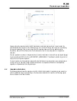
Page 5: ...gain are allowed PHY_ID_CFG_AUTODETECT_IMPEDANCE This allowed variation in gain is not enough to meet injection objective To meet objective in all impedance range with some limitations in low impedan...

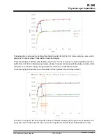
Page 6: ...avoid continuous switching between states which will lead to a continuous change in signal injection which is an undesirable scenario The following figure illustrates such thresholds and the hysteres...

Page 7: ...istortion which compensates the effect of the external driver reducing the ripple to give a final response closer to a flat one Equalization has a tight relation with the Transmission modes seen in pr...

Page 8: ...alization the objective is to get a flatter frequency response of the signal on the band in use for that a maximum ripple must be defined below the customer limits as general rule Microchip recommends...

Page 9: ...ain Value a valid value between the maximum and minimum set on calibration RMS_C RMS Power Calculated RMS_C_C RMS Power Calculated Corrected used for threshold comparing in order to change the TX mode...

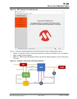
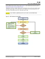
Page 10: ...Process steps CAUTION In each iteration equalization must be reset in order to restore default values Figure 3 4 PHY Calibration Tool Workflow INIT Default Equalization Gain POWER MEASURE RIPPLE MEAS...

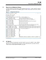
Page 11: ...count the customer calibration Figure 4 1 Configuration File Report 4 1 G3 Projects The PHY Calibration Tool generates a report file atpl360_coup_cfg_G3_ BAND h where BAND depends on the working band...

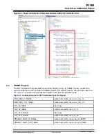
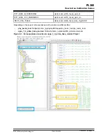
Page 12: ...application code Table 4 1 Correspondence for PHY Calibration Tool File Report MAX_RMS_HI_TABLE static const uint32_t spul_max_rms_hi MAX_RMS_VLO_TABLE static const uint32_t spul_max_rms_vlo TH1_HI_TA...

Page 13: ...e project correspondence will be located on different files phy_tester_tool thirdparty prime_ng phy atpl360 apps phy_tester_tool phy_tester_tool c apps_1_4_prime_base_modem thirdparty prime_ng pal atp...

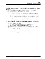
Page 14: ...when PLC output is connected directly to 230 VAC mains Syncp s symbols in G3 power are 3 dB higher than frame symbols The power of payload symbols emitted in PRIME is around 4dB below preamble symbol...

Page 15: ...ries xlswriter pyserial pyvisa xlrd openpyxl pillow matplotlib future Microchip plc_tools_common 2 1 3 Python Library Microchip plc_tools_phy_tester_public 2 0 1 Python Library Microchip plc_tools_uti...

Page 16: ...7 Revision History 7 1 Rev A 10 2018 Document Initial document release PL360 Revision History 2018 Microchip Technology Inc User Guide DS50002818A page 16...

Page 17: ...on and follow the registration instructions Customer Support Users of Microchip products can receive assistance through several channels Distributor or Representative Local Sales Office Field Applicat...

Page 18: ...o CryptoMemory CryptoRF dsPIC FlashFlex flexPWR Heldo JukeBlox KeeLoq Kleer LANCheck LINK MD maXStylus maXTouch MediaLB megaAVR MOST MOST logo MPLAB OptoLyzer PIC picoPower PICSTART PIC32 logo Prochip...

Page 19: ...cilities in Chandler and Tempe Arizona Gresham Oregon and design centers in California and India The Company s quality system processes and procedures are for its PIC MCUs and dsPIC DSCs KEELOQ code h...

Page 20: ...52 China Xiamen Tel 86 592 2388138 China Zhuhai Tel 86 756 3210040 India Bangalore Tel 91 80 3090 4444 India New Delhi Tel 91 11 4160 8631 India Pune Tel 91 20 4121 0141 Japan Osaka Tel 81 6 6152 7160...

Reviews: