background image

Protouch2 GUI User Manual 
 

 2016 Microchip Technology Inc 

Page 10 


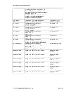
hce_did 

16-bit device release number for HCE device in 
BCD format 

“hce_did”:”0x1234” 

hce_languageid 

Language id of HCE device 

“hce_languageid”:”0x0409” 

hce_manufacturer 

Manufacturer string of HCE device 

“hce_manufacturer”:”Microchip” 

hce_product 

Product string of HCE device 

“hce_product”:”Controller hub” 

hce_serial 

Serial String of HCE device 

“hce_serial”:”123456” 

Additional Configuration items for HSIC Enabled ports of USB3X13 

swapupstreamhsic 

Swap data and strobe in HSIC enabled port 
0 – Enable Swap 
1 – Disable Swap 

“swapupstreamhsic”:”1” 

DOI 


DOIdownstreamport1 
DOIdownstreamport2 
DOIdownstreamport3 

HSIC Driver Output Impedance 
0 – 40 ohm  
1 – 50 ohm 

“DOIdownstreamport1”:”0” 

SLEW 
SLEWdownstreamport1 
SLEWdownstreamport2 
SLEWdownstreamport3 

Slew Tune for HSIC enabled ports 
0 – Default 
1 – +30% 

“SLEWdownstreamport1”:”0” 

Additional Configuration items for USB57x4 

usb3vid 

16-bit value that uniquely identifies the Vendor 
ID of the USB3.1 Gen1


 device 

“usb3vid”:”0x0424” 

usb3pid 

16-bit value that the Vendor can assign that 
uniquely identifies particular Product ID for 
USB3.1 Gen1 device 

“usb3pid”:”0x5744” 

usb3did 

16-bit device release number for USB3.1 Gen1 
device in BCD format 

“usb3did”:”0x5678” 

usb3languageid 

USB3.1 Gen1 LANGUAGE ID 

“usb3languageid”:”0x0409” 

usb3manufacturer 

Manufacturer String of the USB3.1 Gen1 HUB 

“usb3manufacturer”:”Microchip” 

usb3product 

Product String of the USB3.1 Gen1 HUB 

“usb3product”:”USB5734” 

usb3serial 

Serial String of the USB3.1 Gen1HUB 

“usb3serial”:”456789” 

cdcenable


Communication Device class 
Value:0 – Disable CDC 
Value:1 – Enable CDC at interface 1 
Value:2 – Enable CDC at interface 0 

“cdcenable”:”1” 

usb3nrdeviceport1 
usb3nrdeviceport2 
usb3nrdeviceport3 
usb3nrdeviceport4 

Configures Port  as removable/non-removable 
for USB3.1 Gen 1 Ports 
Value : 1 – Port Non-removable 
Value : 0 – Port Removable 

“usb3nrdeviceport”:”1” 

usb3enableport1 
usb3enableport2 
usb3enableport3 
usb3enableport4 

Enable/Disable 3.1 Gen 1 Downstream ports 
Value: 1 – Enable 
Value: 0 – Disable 

“usb3enableport1”:”1” 


Supported configuration items for LAN78XX Family: 
 

Name 

Explanation 

Example 

Configuration items common for  LAN7800 and LAN7850 

macaddr 
 

6-byte universally unique Mac address the board 
will use. Bytes are separated by a colon. 

"macaddr":"00:80:0F:78:50:
04" 

usb2vid 

 16-bit value that uniquely identifies the Vendor of 
the USB2,USB3 user device (Vendor id: assigned by 
USB-Interface) 

“usb2vid”:”0x0424” 

usb2pid 

16-bit value that the Vendor can assign that 
uniquely identifies this particular product for USB2 
,USB3 user device (Product id) 

“usb2pid”:”0x2734” 

Summary of Contents for Protouch2

Page 1: ...Protouch2 GUI User Manual 2016 Microchip Technology Inc Page 1 Protouch2 GUI User Manual...

Page 2: ...Changes from version 1 3 to 1 4 1 5 04 August 2015 Vishnu P Support for USB4604 2534 family added for GUI 1 6 31 March 2016 Mushfira S Added USB bridging with I2C SPI GPIO and UART Added Flex connect...

Page 3: ...Changes 33 11 Programming Page 39 11 1 Device Selection 39 11 2 Configuration programming 39 11 3 Firmware programming 39 11 4 Configuration programming along with SPI Flash Firmware programming 40 1...

Page 4: ...TIES OF MERCHANTABILITY FITNESS FOR A PARTICULAR PURPOSE OR NON INFRINGEMENT IN NO EVENT SHALL MICROCHIP BE LIABLE FOR ANY INCIDENTAL SPECIAL INDIRECT OR CONSEQUENTIAL DAMAGES LOST PROFITS OR LOST DAT...

Page 5: ...Protouch2 GUI User Manual 2016 Microchip Technology Inc Page 5 SD is a trademark of the SD Association in the U S A and other countries...

Page 6: ...talled before connecting the LAN device to computer It is available in PT2 tool folder Drivers LAN78xxDriver install exe 4 Logging Log file with detailed messages will get created in the same path fro...

Page 7: ...ging in the hub and before launching the tool If it is a USB 3 1 Gen1 Hub then power management should be disabled on both USB2 0 Hub and USB 3 1 Gen1 Hub Power Management can be disabled by using the...

Page 8: ...e pid and did are configuration items and 0x1234and 0x5678 are the new values Supported configuration items for USB Hubs Name Explanation Example Configuration items common for USB253x USB4604 USB3X13...

Page 9: ...inal 7 25 above nominal PHYBOOSTdownstreamport1 1 SQUELCH SQUELCHdownstreamp ort1 SQUELCHdownstreamp ort2 SQUELCHdownstreamp ort3 SQUELCHdownstreamp ort4 Configures Varisense of hub 0 Nominal 100mV 1...

Page 10: ...USB3 1 Gen1 device in BCD format usb3did 0x5678 usb3languageid USB3 1 Gen1 LANGUAGE ID usb3languageid 0x0409 usb3manufacturer Manufacturer String of the USB3 1 Gen1 HUB usb3manufacturer Microchip usb...

Page 11: ...or BusPower between 2mA and 100mA for SelfPower HSmaxpower 6 FSinterruptEPinterval Full speed interrupt polling interval The values are in decimal and in the range 0 255 The default value is 1 FSinter...

Page 12: ...ut GPIODirection 20 GPIOData Hex values of GPIO groups 0x0FFF Value 0 low Value 1 high GPIOData 20 GPIOWake Hex values of GPIO groups 0x0FFF Value 0 The GPIO cannot wakeup the device Value 1 The GPIO...

Page 13: ...OBufferType This bit shows the output buffer type for GPIO Value 0 Open drain driver open source Value 1 Push Pull driver Note Buffer Type 0 Polarity 0 implies Open Drain Buffer Type 0 Polarity 1 impl...

Page 14: ...usb3vid 16 bit value that uniquely identifies the Vendor ID of the USB3 1 LAN device usb3vid 0x0424 usb3pid 16 bit value that the Vendor can assign that uniquely identifies particular Product ID for U...

Page 15: ...line is selected in landing page it moves to the USB253X 8 480X 3X13 online hub configuration page and looks for USB253X 8 480X 3X13 Microchip Hubs in the system after loading the appropriate drivers...

Page 16: ...Hub Devices 10 1 Online Hub Configuration Page MCHP hubs contain several registers that can change the behavior of the hub It can be changed to a new value through the PT2 application by programming t...

Page 17: ...USB57x4 is 8KB Auto Identified Part Number This will give information about the SKU which is nothing but default PID of the SKU The Auto identification is independent of VID PID changes Configuration...

Page 18: ...pt to restore the device to its original manufacturer settings For USB253x SKU if Number of configuration programmed is 16 and running from ROM then Protouch2 will ask for default SKU to restore 10 1...

Page 19: ...riptors and UUID can be customized by writing appropriate values 10 1 5 Downstream Port Configuration The hubs USB253X 8 460X 57X4 have 4 downstream ports The SKUs USB3X13 USB3613 and USB3813 only hav...

Page 20: ...or disabled GUI will remap appropriate logical ports internally Non Removable ports USB 2 0 ports can be configured as Non Removable ports It indicates whether the ports have non removable devices If...

Page 21: ...Compliant Port Max 1 5A When there is no upstream VBUS and consequently no USB host connected on the upstream port the downstream battery charging enabled ports will operate as BC 1 2 compliant Port...

Page 22: ...0 DP and DM Pins can be swapped using GUI PHY Boost and Varisense USB signal drive strength in upstream and downstream transceivers can be changed using PHY Boost USB signal receiver sensitivity can...

Page 23: ...lowing are the HSIC related configurations which can be done on HSIC enabled ports Swap HSIC DATA STROBE HSIC Data and Strobe Pins can be swapped using GUI HSIC Driver Output Impedance HSIC Driver Out...

Page 24: ...tream port is downstream port and downstream port1 is the upstream port Swap D D USB 2 0 Upstream DP and DM Pins can be swapped using the GUI PHY Boost and Varisense USB signal drive strength in upstr...

Page 25: ...check box is checked UCH Enabled always UCH Vendor id Product id bcdDevice and String Descriptors can be customized by writing appropriate values If the VID or PID of the HCE device is changed from th...

Page 26: ...t Enabled always If check box is checked CDC Enabled always When WinUSB interface is present CDC will enumerate at interface 1 otherwise at interface 0 Note CDC is not available for USB253X USB4604 10...

Page 27: ...r mode is configured as a Bus Powered device the Hub consumes less than 100mA of current prior to being configured After configuration the Bus Powered Hub along with all associated hub circuitry any e...

Page 28: ...is enabled then Device is configured and is active not in suspend If Resume inhibit is enabled then if hub detects any wakeup event then suspend indication will be driven for some time SUSP_IND Pin ca...

Page 29: ...ccess option This method follows Big endian Example Write value 1234 in register 0x3000 as shown below Here 12 will be written to 0x3000 and 34 will be written to 0x3001 Alternatively ini file can be...

Page 30: ...x3000 XCLR_3001 01 clears bit 2 in xdata address 0x3001 Example 2 XCLR_3000 01 40 clears bit 2 in xdata address 0x3000 and clears bit 5 in xdata address 0x3001 Note 1 Follow either one of the example...

Page 31: ...r Manual 2016 Microchip Technology Inc Page 31 Example To read Register value Advanced Option Values read are stored in File selected This file can be used as an input when Write Option is selected 10...

Page 32: ...p memory allows user to dump OTP memory or SPI memory or SPI with Pseudo OTP memory present in device connected OTP Memory Dump will be saved in a given file with extension dump and SPI Memory SPI wit...

Page 33: ...x Feature Command to the Hub Both USB2530 as well as USB57x4 Hub will respond to valid Flexconnect command 10 3 Preview Changes Preview changes allows user to view information such as Number of bytes...

Page 34: ...Live Flexconnect USB 2 0 USB 3 1 Gen1 Downstream Port 1 can be configured as Upstream Port and upstream port can be configured as downstream Port 1 If check box is not checked Upstream port is not Fl...

Page 35: ...ser Manual 2016 Microchip Technology Inc Page 35 10 3 3 USB I2C Bridge Demo Microchip USB hubs facilitate USB I2C bridging through USB control point of the embedded USB device 5th port Example To do I...

Page 36: ...rt address and 11 22 is the data that is to be written Step 2 After this do a write again for slave address 0x50 data 00 and length 1 Step 3 Now do an I2C read 10 3 4 USB SPI Bridge Demo SPI Read Here...

Page 37: ...but a XDATA read from a specified offset where the response is stored SPI transfer demo can be done only when the USB hub boots up from ROM SPI Send Operation SPI Receive Operation 10 3 5 USB GPIO Br...

Page 38: ...Technology Inc Page 38 GPIO Get Operation This demo allows us to get the state of a specified GPIO pin 10 3 6 USB UART Bridge Demo UART demo The data is transferred through a serial port to the connec...

Page 39: ...iguration file generated in Offline Page can be used as input 11 3 Firmware programming Firmware programming is required only if user intends to program the SPI flash Otherwise this section can be ski...

Page 40: ...Types of programming 11 5 1 Program Once Single device can be programmed at a time by using Program Once option Select the hub of interest Configuration file and or Firmware File should be selected be...

Page 41: ...Inc Page 41 11 5 3 Programming time It takes about 3 to 5 seconds for programming if the internal HCE Hub Controller Enumeration device is enabled Otherwise it takes about 14 to 20 seconds depending o...

Page 42: ...Select the part number of interest from the drop down shown below Loading a configuration file on top of the default SKU settings If user wants to generate configuration file for a device whose config...

Page 43: ...gs of the hub as desired can be changed from the default or default Load configuration settings as shown below The SAVE button becomes active as soon as any changes are done RESET If the changes are t...

Page 44: ...Protouch2 GUI User Manual 2016 Microchip Technology Inc Page 44...

Page 45: ...e device can enumerate and it is EEPROM Less mode Online Configuration page in GUI does not support this mode And in case if the device is factory default that is it either has blank OTP or blank EEPR...

Page 46: ...ges Configuration memory LAN78XX device has two types of configuration memory EEPROM and OTP If EEPROM memory is enabled in device all the configuration values are loaded from EEPROM If OTP memory is...

Page 47: ...or LAN7850 the Device Descriptor fields configure USB 2 0 VID USB 2 0 PID USB 2 0 DID For LAN7800 the Device Descriptor fields configure both the USB 2 0 and USB 3 0 VIDs PIDs DIDs USB String Descript...

Page 48: ...des below Link Activity LED will monitor the Link at any speed and its activity Link1000 Activity LED will monitor the Link in 1000BASE T and its activity Link100 Activity LED will monitor the Link in...

Page 49: ...ault in Link Serial Mode LED will monitor the Serial Stream Force LED OFF This will De assert the LED Force LED ON This will assert the LED All the Four LEDs LED0 LED1 LED2 LED3 behaviour can be confi...

Page 50: ...onfiguration GPIO Configuration fields are used to Enable Disable the all the 7 GPIOs GPIO0 GPIO1 GPIO2 GPIO3 GPIO4 GPIO5 GPIO6 Output buffer for the GPIO Pins can be configured as a push pull driver...

Page 51: ...is set as Output Output value has to be given in the GPIO data field When the GPIO is set as Input GPIO data field will be hidden 13 1 2 5 Power Management LAN78XX can wake up the Host Processor via d...

Page 52: ...set in GPIO PME length GPIO PME can be enabled for desired GPIO using the GPIO Wake Up field and the polarity can be set in GPIO Wake up polarity PHY Link Change Detection of a PHY link partner when i...

Page 53: ...isters and PHY registers Register Address and the length of bytes to read write is given in Register Address and Length fields 13 1 2 7 OTP EEPROM Dump Memory Dump memory allows user to dump OTP memor...

Page 54: ...Programming Page enables the user to program configuration file in EEPROM and OTP memory 13 1 4 1 Program Once Single device can be programmed at a time by disabling the Enable Mass Program Select th...

Page 55: ...n file Example for Single Programming Serial Number in Single Programming Prefix MCHP Start 1 MAC Address in Single Programming Start 00 80 0F 78 00 02 If the above values are given then Device 1 will...

Page 56: ...e with MAC address alone Configuration file will be programmed in either OTP or EEPROM with the given MAC address overwriting the values in configuration file Example for Mass Programming Serial Numbe...

Page 57: ...neration of configuration file even without the hub being connected to the system Selecting Offline mode Select the radio button on the landing page as shown below Selecting the part number Select the...

Page 58: ...nfiguration file for a device whose configuration is already modified then that device s dump file should be loaded using Load Configuration file option This should be done before any changes are done...

Page 59: ...nge configuration settings Configuration settings of the hub as desired can be changed from the default or default Load configuration settings as shown below The SAVE button becomes active as soon as...

Page 60: ...like mouse or pen drive to one of the downstream ports to prevent the hub from going to sleep 3 If you are still having issues please email the PT2 log file created in the same directory as the tool...

Page 61: ...I pass through Enter command failed 1 0x1005 SPI flash could not be detected or was not present 0x1006 SPI Cancel Download 0x1007 SPI flash programming failed 0x1008 SPI pass through Enter command fai...

Page 62: ...n failed 0x4007 UART Rx is pending due to asynchronous mode 0x4008 UART receive aborted as per user request 0x4009 UART Receive command failed by the firmware 0x400A Receive failed without receiving a...

Page 63: ...Protouch2 GUI User Manual 2016 Microchip Technology Inc Page 63 15 Appendix II Disable Power Management 16 Windows 7 1 Right click My Computer and choose Manage 2 Select Device Manager...

Page 64: ...Protouch2 GUI User Manual 2016 Microchip Technology Inc Page 64 3 Search the hub based upon the VID PID 4 Select the hub and Right click on it choose Properties option...

Page 65: ...touch2 GUI User Manual 2016 Microchip Technology Inc Page 65 5 Select Power Management option 6 To disable a Power Management uncheck the checkbox Allow the computer to turn this device off to save po...

Page 66: ...rochip Technology Inc Page 66 7 Repeat the procedure Steps 3 to 6 for USB 3 0 MTT hub if the connected hub is USB3 1 Gen1 Hub 17 Windows 8 1 Right click Mycomputer and choose Manage option All the oth...

Page 67: ...tall PT2 drivers and can start using PT2 GUI or CLI PT1 and PT2 use different drivers Hence after installing PT2 if user wants to use PT1 the drivers have to be restored as given below 1 Open PT1 Tool...

Page 68: ...Protouch2 GUI User Manual 2016 Microchip Technology Inc Page 68 5 Select SMSC WinUSB Device 6 Now WinUSB Device will be loaded with SMSC WinUSB device driver...

Page 69: ...Protouch2 GUI User Manual 2016 Microchip Technology Inc Page 69 7 Now User can use PT1 tool 8 Install the PT2 drivers for running PT2...

Page 70: ...chip Technology Inc Page 70 19 Appendix IV Checking whether drivers were installed correctly for PT2 To check whether the drivers VSM and WinUSB were installed correctly 20 VSM as Class Filter 1 Right...

Page 71: ...Protouch2 GUI User Manual 2016 Microchip Technology Inc Page 71 2 It will navigate to Computer Management Window In this click Device Manager...

Page 72: ...Protouch2 GUI User Manual 2016 Microchip Technology Inc Page 72 3 Select any one of the hub right click on it and choose Properties...

Page 73: ...Protouch2 GUI User Manual 2016 Microchip Technology Inc Page 73 4 It will open Properties of the Hub Choose Driver tab...

Page 74: ...Microchip Technology Inc Page 74 5 In the Driver tab click Driver Details option It will redirect to Driver File details dialogue box 6 If the VSM driver was installed as a class filter there will be...

Page 75: ...ay take few seconds to load the WinUSB driver While it is loading its status can be monitored in the device manager Following are the steps to check the installation of WinUSB driver 1 HCE Internal US...

Page 76: ...Protouch2 GUI User Manual 2016 Microchip Technology Inc Page 76 2 To check the Driver version Right click the HCE in device manager and click Properties...

Page 77: ...Protouch2 GUI User Manual 2016 Microchip Technology Inc Page 77 3 It will open Microchip Hub Controller properties...

Page 78: ...Protouch2 GUI User Manual 2016 Microchip Technology Inc Page 78 4 In the Properties of Microchip Hub controller we can find the driver Version The driver version should be 1 0 0 4...

Reviews: