background image

Lab Manual for TCP 17051 


Page | 18 

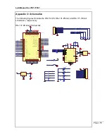
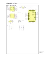
Appendix C: Schematics 

 
The following figures illustrate the RN-131-EK, RN-131-PICtail, and RN-171-PICtail 
schematics, respectively. 
 

RN-131 EK Board Schematic 


SENS OR _P OW E R

SENSOR _4

SENSOR _5

SENSOR _7

SENSOR _6

SENSOR _5

SENSOR _4

SENSOR4_ P IN

SENSOR5_ P IN

SENSOR _0

SENSOR _1

SENSOR _3

SENSOR _2

GPIO _9

RX D

CT S

100k

R16

100k

R9

100k

R6

100k

R7

100k

R14

220k

R5

220k

R10

220k

R15

220k

R8

220k

R11

1

2

3

4

5

6

7

8

9

J1

Sensor  Interface

VDD_3V3

GPIO _8

GPIO _5

GPIO _6

GPIO _7

GPIO _4

RESET _N

GPIO _9

TX D

RX D

CT S

RT S

1

2

3

4

5

6

7

8

9

10

11

12

13

J3

UART  I nterface

VBUS

D_N

D_P

TXD

RXD

RTS

CTS

VBUS

RESET 18

3V

3O

U

T

16

USBDP 14

USBDM 15

GN

D

17

CBUS2

10 CBUS1

21

VC

C

IO

1

CBUS3

11

CBUS4

9

CBUS0

22

GN

D

20

RI

3 DCD

7 DSR

6 DTR

31 CTS

8 RTS

32 RXD

2 TXD

30

VC

C

19

OSCI 27

OSCO 28

AG

N

D

24

TES

T

26

GN

D

4

TH

PA

D

33

FT232RQ

U1

100nF

C2

100nF

C3

100nF

C1

GND

5

D+

3 D-

2 VBUS

1

MTAB 6

USB  Mini  B

J2

i

Power  Net

i Power  Net

3k3

R1

3k3

R3

3k3

R2

3k3

R4

GPIO _5

GPIO _6

GPIO _4

GPIO _6

GPIO _5

GPIO _4

GPIO _7

GPIO _8

GPIO _7

220R

R21

220R

R23

220R

R17

220R

R13

100k

R20

100k

R18

100k

R12

100k

R19

100k

R22

Blue

D4

Green

D3

Yellow

D2

Red

D1

VDD_3V3

GPIO _9

S1

S2

RESET _N

SENSOR _0

SENSOR _1

SENSOR _2

SENSOR _3

SENSOR _6

SENSOR _7

SENSOR _4

SENSOR _5

SENS OR _P OW E R

RESET _N

FOR C E _AW AKE

GPIO _8

GPIO _9

GPIO _5

GPIO _6

GPIO _7

GPIO _4

CT S

RT S

TX D

RX D

VDD_3V3

29        GPI

O_4

29

30        SENSOR_1

30

31        SENSOR_2

31

32        SENSOR_3

32

33        SENSOR_POWER

33

34        SENSOR_0

34

36 


G

N

D

36

EPC_A            6

6

EPC_B            7

7

SUPERCAP_BAL ANCE            8

8

FORCE_AWAKE            99

UART_RTS(GPI O_13)          10

10

UART_CTS(GPI O_12)          11

11

UART_RX(GPI O_11)          12

12

UART_TX  (GPI O_10)          13

13

SENSOR_6            1

1

SENSOR_4            2

2

SENSOR_5            3

3

SENSOR_7            4

4

RESET            55

SP

I_

M

O

SI


 1

4

14

SP

I_S

C

K


 1

5

15

SP

I_

M

ISO


 1

6

16

SR

E

G

_O

U

T


 1

7

17

SR

E

G

_I

N


 1

8

18

GN

D


 1

9

19

BA

T

T


20

20

VD

D


21

21

IS

P_T

X


 2

2

22

23        I

SP_RX

23

24        GPI

O_9

24

25        GPI

O_8

25

26        GPI

O_7

26

27        GPI

O_6

27

28        GPI

O_5

28

37 


G

N

D

37

38 


G

N

D

38

39 


G

N

D

39

40 


G

N

D

40

41 


G

N

D

41

42 


G

N

D

42

43 


G

N

D

43

44 


G

N

D

44

M1

RN131  Module

100nF

C4

VBUS

i Power  Net

Vin

1

G

ND

2

Vout 3

Ta

b

4

TC1262- 3.3VDBTR

U2

VDD_3V3

i Power  Net

Summary of Contents for TCP 17051

Page 1: ...Lab Manual for TCP 17051 Table of Contents Hardware Architecture 2 Lab 1 Instructions 4 Appendix A Command Reference 12 Appendix B Reference documents 17 Appendix C Schematics 18 Adding Wi Fi to Embe...

Page 2: ...nly 6 Sensor 4 1 2 V only 7 Sensor 6 1 2 V only 8 Sensor 3 1 2 V only 9 GND WARNING Sensors must not have more than 1 2 V DC Otherwise the module may be permanently damaged Table 1 RN 131 EK Evaluatio...

Page 3: ...to interface the RN 131 EK to the PC Access point s configured with WAP2 security this hardware is already set up in the lab by the instructor Software Tera Term software http sourceforge jp projects...

Page 4: ...ransmission over TCP Purpose This lab will teach you how to Configure the module s parameters Scan join and authenticate to wireless networks Discover the WiFly module on your wireless network via UDP...

Page 5: ...via UDP broadcast 5 Send data to your lab partner using TCP Part 1 Hardware Setup 1 Connect the evaluation board a Connect the RN 131 EK board to your computer using the USB cable b Use the device ma...

Page 6: ...on and initialize the module to the factory default conditions a Check the configuration and firmware version i ver b Perform a factory reset starts the module in a known state i factory RESET ii rebo...

Page 7: ...2100 00 00 d8 c7 c8 aa e7 a1 guest 09 06 57 08 3100 28 00 d8 c7 c8 aa e7 a2 mchp secure 10 06 52 04 3104 28 00 b8 c7 5d 06 d0 2b 11 06 53 04 3104 28 00 00 26 f2 4f 89 d6 roving guest 12 09 49 04 3104...

Page 8: ...0 set wlan ssid roving1 AOK 4 00 set wlan pass rubygirl AOK 4 00 set wlan join 1 AOK 4 00 save Storing in config 4 00 reboot Reboot wifly GSX Ver 4 00 1 Apr 19 2013 11 48 28 on RN 131 MAC Addr 00 06 6...

Page 9: ...ce 192 168 0 2 192 168 0 1 174 201 25 16 To Internet Roving Networks Device Roving Networks Device Roving Networks Device Roving Networks Device Roving Networks Device 192 168 0 4 192 168 0 5 192 168...

Page 10: ...re TCP Connections 1 Restore the module to the factory defaults a Enter command mode b factory RESET Restore module to factory defaults c reboot Reboot module with factory defaults 2 Associate with AP...

Page 11: ...isten on 2000 My module s IP address ________________________ 4 Student A open a TCP connection to your lab partner a Enter command mode b open Lab Partner IP address 2000 2000 is the port number OPEN...

Page 12: ...that is sent to the local UART when the TCP port is opened set comm remote string HELLO Sets the ASCI string that is sent to the remote TCP client when the TCP port is opened set comm size value 64 Se...

Page 13: ...RN131 and EZX for the RN171 set opt format flag 0x00 Sets the HTTP client web server information set opt jointmr value 1000 Sets the join timer which is the length of time in ms the join function wai...

Page 14: ...value Not applicable Disables or enables the UART s TX pin GPIO10 where value is 1 or 0 set wlan auth value 0 Sets the authentication mode set wlan channel value flag 0 Sets the WLAN channel where va...

Page 15: ...ys the system settings sleep and wake timers etc get time Displays the time server UDP address and port number get wlan Displays the SSID channel and other WLAN settings get uart Displays the UART set...

Page 16: ...address value Opens a TCP connection to address where value is the port number ping string value Pings a remote host where string is a parameter setting and value is the number of pings The default i...

Page 17: ...mation refer to the following documentation WiFly Command Reference Advanced Features Applications User s Guide RN 131G RN 131C 802 11 b g Wireless LAN Module Data Sheet RN 171 802 11 b g Wireless LAN...

Page 18: ...3k3 R1 3k3 R3 3k3 R2 3k3 R4 GPIO _5 GPIO _6 GPIO _4 GPIO _6 GPIO _5 GPIO _4 GPIO _7 GPIO _8 GPIO _7 220R R21 220R R23 220R R17 220R R13 100k R20 100k R18 100k R12 100k R19 100k R22 Blue D4 Green D3 Y...

Page 19: ...22 220k R21 PIC_TX 10uF C3 10uF C4 VDD3V3 Vin 1 GND 2 Vout 3 T ab 4 TC1262 3 3V U2 Vin i Power Net 220R R18 Green L E D D4 ST A T US_L E D 220R R19 R ed L E D D5 PIC_L E DR 220R R20 PIC_L E DY Y ellow...

Page 20: ...220R R10 Green L E D D1 ST A T US_L E D 220R R9 R ed L E D D2 PIC_L E DR 220R R11 PIC_L E DY Y ellow L E D D3 SEN0 100k R7 220k R6 PIC_TX ISP_ TX ISP_ R X 1 2 3 4 5 6 7 8 J3 ISP Connector UART_TX PIC...

Reviews: