2-Port USB 2.0 Hi-Speed Hub Controller
Datasheet
2014 Microchip Technology Inc.
DS00001726A-page 21
7. The PLL is halted.
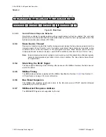
4.2.1.1
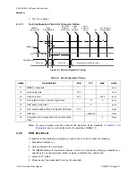
Hub Configuration Timing for Strapping Option
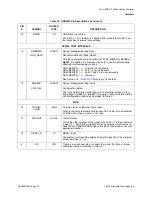
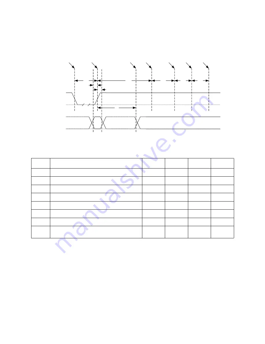
Figure 4.1 Hub Configuration Timing
Note:
All power supplies must have reached the operating levels mandated in
, prior to (or coincident with) the assertion of
RESET_N
.
4.2.2
USB Bus Reset
In response to the upstream port signaling a reset to the hub, the hub does the following:
1. Sets default address to
0
.
2. Sets configuration to unconfigured.
3. The
PRTPWR
power to downstream devices is turned on when battery charging is enabled for a
specific port, and removed when battery charging is disabled for a specific port.
4. Clears all TT buffers.
5. Moves device from suspended to active (if suspended).
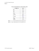
Table 4.2 Hub Configuration Timing
NAME
DESCRIPTION
MIN
TYP
MAX
UNITS
t1
RESET_N
asserted
1
μ
sec
t2
Strap setup time
16.7
nsec
t3
Strap hold time
16.7
1400
nsec
t4
Hub outputs driven to inactive logic states
1.5
2
μ
sec
t5
USB attach (See Note)
3
μ
sec
t6
Host acknowledges attach and signals USB reset
100
msec
t7
USB idle
undefined
msec
t8
Completion time for requests (with or without data
stage)
5
msec
t1
t4
t5
t6
t7
t8
Valid
Driven by Hub if strap is an output
RESET_N
VSS
NON_REM[1:0]
VSS
Hardware
reset asserted
Read
NON_REM[1:0]
Drive Strap
Outputs to
inactive levels
Attach
USB
Upstream
Attach
Debounce
Interval
Idle
Start completion
request response
t2
t3
Don’t Care
Don’t Care

