2-Port USB 2.0 Hi-Speed Hub Controller
Datasheet
DS00001726A-page 22
2014 Microchip Technology Inc.
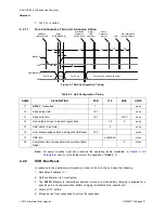
6. Complies with Section 11.10 of the
USB 2.0 Specification
for behavior after completion of the reset
sequence. The host then configures the hub and the hub’s downstream port devices in accordance
with the specification.
The hub does not propagate the upstream USB reset to downstream devices.
4.3
SMBus
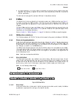
The Microchip hub can be configured by an external processor via an SMBus interface (see
for details on enabling the SMBus interface). The Microchip hub waits indefinitely for the SMBus code
load to complete and only appears as a newly connected device on USB after the code load is
complete.
The hub’s SMBus acts as a slave-only SMBus device. The implementation only supports block write
(
) and block read (
) protocols. Reference the
System Management Bus
Specification
for additional information.
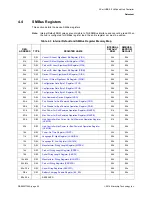
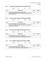
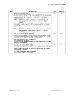
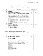
Section 4.4, "SMBus Registers," on page 24
for details on all SMBus accessible registers.
4.3.1
SMBus Slave Address
The 7-bit slave address is 0101100b. The hub will not respond to the general call address of 0000000b.
4.3.2
Protocol Implementation
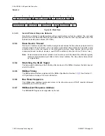
Typical block write and block read protocols are shown in figures
and
. Register accesses are
performed using 7-bit slave addressing, an 8-bit register address field, and an 8-bit data field. The
shading shown in the figures during a read or write indicates the hub is driving data on the
SMBDATA
line; otherwise, host data is on the
SMBDATA
line.
The SMBus slave address assigned to the hub (0101100b) allows it to be identified on the SMBus.
The register address field is the internal address of the register to be accessed. The register data field
is the data that the host is attempting to write to the register or the contents of the register that the
host is attempting to read.
Note:
Data bytes are transferred MSB first.
4.3.2.1
Block Write/Read
The block write begins with a slave address and a write condition. After the command code, the host
issues a byte count which describes how many more bytes will follow in the message. If a slave had
20 bytes to send, the first byte would be the number 20 (14h), followed by the 20 bytes of data. The
byte count may not be zero. A block write or read allows a transfer maximum of 32 data bytes.
Note:
For the following SMBus tables:
Figure 4.2 Block Write
4.3.2.2
Block Read
A block read differs from a block write in that the repeated start condition exists to satisfy the SMBus
specification’s requirement for a change in the transfer direction.
Denotes Master-to-Slave
Denotes Slave-to-Master
S
Slave Address
Register Address
Wr
A
1
7
1
1
8
A
1
...
1
8
1
Byte Count = N
A
Data byte 1
A
Data byte 2
A
8
1
1
1
8
8
Data byte N
A
P


