background image

2-Port USB 2.0 Hi-Speed Hub Controller

Datasheet

 2014 Microchip Technology Inc.

DS00001726A-page 29

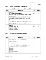
4.4.8

Configuration Data Byte 2 Register (CFG2)

Address:

07h

Size:

8 bits

BITS

DESCRIPTION

TYPE

DEFAULT

7

Dynamic Power Enable (DYNAMIC)

Controls the ability of the Hub to automatically change from Self-Powered 

operation to Bus- Powered operation if the local power source is removed 

or is unavailable (and from Bus-Powered to Self-Powered if the local power 

source is restored).

Note:

If the local power source is available, the Hub will always switch to 
Self-Powered operation.

When Dynamic Power switching is enabled, the Hub detects the availability 

of a local power source by monitoring the external LOCAL_PWR pin. If the 

Hub detects a change in power source availability, the Hub immediately 

disconnects and removes power from all downstream devices and 

disconnects the upstream port. The Hub will then re-attach to the upstream 

port as either a Bus-Powered Hub (if local-power is unavailable) or a Self-

Powered Hub (if local power is available).

0 = No Dynamic auto-switching

(pin becomes SUSP_IND) and the hub controller will utilize the inverse of 

the SELF_BUS_PWR bit for 'Hub_Status_Field' bit '0' (local power source)

1 = Dynamic Auto-switching capable

(pin becomes LOCAL_PWR) and the hub controller will utilize the 

LOCAL_PWR pin for 'Hub_Status_Field' bit '0' (local power source)

R/W

0b

6

RESERVED

-

-

5:4

Over Current Timer Delay (OC_TIMER)

00 = 0.1ms

01 = 4ms

10 = 8ms

11 = 16ms

R/W

00b

3

Compound Device (COMPOUND)

Allows the OEM to indicate that the Hub is part of a compound (see the USB 

Specification for definition) device. The applicable port(s) must also be 

defined as having a “Non-Removable Device”.

Note:

When configured via strapping options, declaring a port as non-
removable automatically causes the hub controller to report that it 
is part of a compound device.

0 = No

1 = Yes, Hub is part of a compound device

R/W

0b

2:0

RESERVED

-

-

Summary of Contents for USB2422

Page 1: ...n chip driver for 24 MHz crystal resonator or external 24 MHz clock input ESD protection up to 6 kV on all USB pins Supports self powered operation The hub contains a built in default configuration no...

Page 2: ...e version number e g DS30000000A is version A of document DS30000000 Errata An errata sheet describing minor operational differences from the data sheet and recommended workarounds may exist for cur r...

Page 3: ...xadecimal number value zz rsvd Reserved memory location Must write 0 read value indeterminate code Instruction code or API function or parameter Section Name Section or Document name x Don t care Para...

Page 4: ...23 4 3 6 Bus Reset Sequence 23 4 3 7 SMBus Alert Response Address 23 4 4 SMBus Registers 24 4 4 1 Vendor ID Least Significant Bit Register VIDL 25 4 4 2 Vendor ID Most Significant Bit Register VIDM 25...

Page 5: ...rial String Registers SERSTR 35 4 4 26 Battery Charging Enable Register BC_EN 35 4 4 27 Boost Upstream Register BOOSTUP 36 4 4 28 Boost Downstream Register BOOST40 36 4 4 29 Port Swap Register PRTSP 3...

Page 6: ...Application SoC Based Design 16 Figure 2 6 Example Application Non SoC Based Design 16 Figure 3 1 Battery Charging via External Power Supply 18 Figure 4 1 Hub Configuration Timing 21 Figure 4 2 Block...

Page 7: ...n Descriptions 11 Table 2 3 Buffer Type Descriptions 14 Table 2 4 Strap Option Summary 14 Table 2 5 Example Applications Resistor Capacitor Values 17 Table 4 1 Hub Configuration Options 20 Table 4 2 H...

Page 8: ...3 3V Upstream PHY Upstream USB Data Repeater Controller SIE Serial Interface PLL 24 MHz Crystal To SMBus Master Routing Port Re Ordering Logic SMBCLK SMBDATA Port Controller Bus Power Detect VBUS Puls...

Page 9: ...at a high voltage level The terms assertion and negation are used exclusively in order to avoid confusion when working with a mixture of active low and active high signals The term assert or assertio...

Page 10: ...VBUS_DET DOWNSTREAM 2 PORT USB 2 0 INTERFACES 9 PINS USBDP_DN1 PRT_DIS_P1 USBDM_DN1 PRT_DIS_M1 USBDP_DN2 PRT_DIS_P2 USBDM_DN2 PRT_DIS_M2 PRTPWR1 BC_EN1 PRTPWR2 OCS1_N OCS2_N RBIAS SERIAL PORT INTERFAC...

Page 11: ...le Strap Option If this strap is enabled by package and configuration settings see Table 4 1 Hub Configuration Options this pin will be sampled at RESET_N negation to determine if the port is disabled...

Page 12: ...onfiguration Select The logic state of this multifunction pin is internally latched on the rising edge of RESET_N RESET_N negation and will determine the hub configuration method as described in Table...

Page 13: ...of local power input only if properly configured via SMBus If the hub is configured via straps it is NON_REM0 at reset and SUSP_IND after reset NON_REM0 Non Removable Port Strap Option This pin is sam...

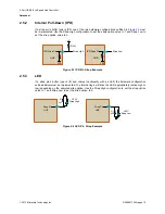
Page 14: ...ption to 0 When implementing the Strap Low option no additional components are needed i e the internal pull down provides the resistor Figure 2 2 Non Removable Pin Strap Example Table 2 3 Buffer Type...

Page 15: ...gure 2 3 IPD Pin Strap Example 2 5 3 LED If a strap pin s buffer type is I O and shares functionality with an LED the hardware configuration outlined below must be implemented The internal logic will...

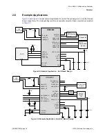
Page 16: ...SMBCLK SMBDATA RESET_N XTALOUT XTALIN SUSP_IND RBIAS VDD33 1 9 18 PLLFILT CRFILT N C PRTPWR1 OCS1_N USBDP_DN1 USBDM_DN1 PRTPWR2 11 OCS2_N 12 USBDP_DN2 USBDM_DN2 GND RBIAS CBYP COUTCR COUTPLL Vcc USB...

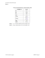
Page 17: ...2 1 COUTCR should be placed as close as possible to pin 9 Note 2 2 COUTPLL should be placed as close as possible to pin 1 Table 2 5 Example Applications Resistor Capacitor Values DESIGNATOR VALUE R1...

Page 18: ...llows a device to perform battery charging at any time A port that supports battery charging must be able to support 1 5 amps of current on VBUS Standard USB port power controllers typically only allo...

Page 19: ...s for details Section 2 3 Pin Descriptions Grouped by Function on page 11 Section 2 5 Strap Pin Configuration on page 14 When the hub is initialized for configuration over SMBus 3 2 1 Battery Charging...

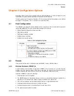
Page 20: ...hardware reset is defined as assertion of RESET_N for a minimum of 1 s after all power supplies are within operating range While reset is asserted the hub and its associated external circuitry consum...

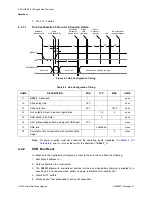
Page 21: ...cific port and removed when battery charging is disabled for a specific port 4 Clears all TT buffers 5 Moves device from suspended to active if suspended Table 4 2 Hub Configuration Timing NAME DESCRI...

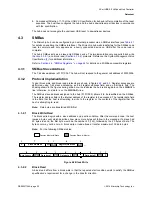
Page 22: ...ccesses are performed using 7 bit slave addressing an 8 bit register address field and an 8 bit data field The shading shown in the figures during a read or write indicates the hub is driving data on...

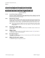
Page 23: ...new START condition no later than 35 ms TTIMEOUT MAX Note Some simple devices do not contain a clock low drive circuit this simple kind of device typically resets its communications port after a star...

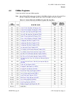
Page 24: ...ation Data Byte 2 Register CFG2 20h 00h 08h R W Configuration Data Byte 3 Register CFG3 02h 00h 09h R W Non Removable Device Register NRD 00h 00h 0Ah R W Port Disable for Self Powered Operation Regist...

Page 25: ...bits BITS DESCRIPTION TYPE DEFAULT 7 0 Least Significant Byte of the Vendor ID VID_LSB This is a 16 bit value that uniquely identifies the Vendor of the user device assigned by USB Interface Forum Th...

Page 26: ...00h Address 03h Size 8 bits BITS DESCRIPTION TYPE DEFAULT 7 0 Most Significant Byte of the Product ID PID_LSB This is a 16 bit value that the Vendor can assign that uniquely identifies this particular...

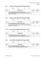
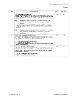
Page 27: ...ce 1mA of upstream VBUS current is consumed and all ports are available with each port being capable of sourcing 500mA of current This field is set by the OEM using the SMBus interface option Please s...

Page 28: ...It is included because it is a permitted feature in Chapter 11 of the USB specification R W 0b 2 1 Over Current Sense CURRENT_SNS Selects current sensing on a port by port basis all ports ganged or n...

Page 29: ...isconnects the upstream port The Hub will then re attach to the upstream port as either a Bus Powered Hub if local power is unavailable or a Self Powered Hub if local power is available 0 No Dynamic a...

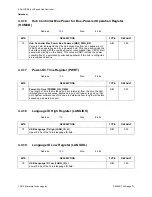
Page 30: ...Operation Reset 0x00 Register 0Bh Port Disable For Bus Powered Operation Reset 0x00 1 Port Re Map mode The mode enables remapping via Register FBh Port Remap 12 R W 0b 2 1 RESERVED 0 String Enable ST...

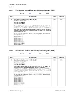
Page 31: ...efault option the PRT_DIS 1 0 pins will disable the appropriate ports Bit 7 Reserved Bit 6 Reserved Bit 5 Reserved Bit 4 Reserved Bit 3 Reserved Bit 2 Port 2 Disable Bit 1 Port 1 Disable Bit 0 Reserve...

Page 32: ...h Address 0Dh Size 8 bits BITS DESCRIPTION TYPE DEFAULT 7 0 Max Power Bus Powered MAX_PWR_BP Value in 2mA increments that the Hub consumes from an upstream port VBUS when operating as a self powered h...

Page 33: ...associated circuitry on the board This value will NOT include the power consumption of a permanently attached peripheral if the hub is configured as a compound device R W 00h Address 10h Size 8 bits...

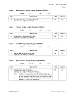
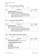
Page 34: ...ing Length PRD_STR_LEN Maximum string length is 31 characters R W 00h Address 15h Size 8 bits BITS DESCRIPTION TYPE DEFAULT 7 0 Serial String Length SER_STR_LEN Maximum string length is 31 characters...

Page 35: ...r R W 00h Address 92h CFh Size 8 bits BITS DESCRIPTION TYPE DEFAULT 7 0 Serial String SER_STR UNICODE UTF 16LE per USB 2 0 Specification Maximum string length is 31 characters 62 Bytes Note The String...

Page 36: ...rical drive strength 12 boost R W 00b Address F8h Size 8 bits BITS DESCRIPTION TYPE DEFAULT 7 4 RESERVED 3 2 Boost Downstream Port 2 BOOST_IOUT_2 USB electrical signaling drive strength Boost Bit for...

Page 37: ...USB DP and DM Pins for ease of board routing to devices and connectors 0 USB D functionality is associated with the DP pin and D functionality is associated with the DM pin 1 USB D functionality is a...

Page 38: ...hysical Port Number When remapping mode is enabled PRTMAP_EN in the Configuration Data Byte 3 Register CFG3 the hub s downstream port numbers can be remapped to different logical port numbers assigned...

Page 39: ...s the SMBus Interface and internal memory back to RESET_N assertion default settings 0 Normal Run Idle State 1 Force a reset of the registers to their default state Note During this reset this bit is...

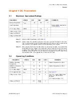
Page 40: ...e AC power is switched on or off In addition voltage transients on the AC power line may appear on the DC output When this possibility exists it is suggested that a clamp circuit be used 5 2 Operating...

Page 41: ...resis IS only VHYSI 250 350 mV Input Buffer with Pull Up IPU Low Input Level VILI 0 8 V TTL Levels High Input Level VIHI 2 0 V Low Input Leakage IILL 35 90 A VIN 0 High Input Leakage IIHL 10 10 A VIN...

Page 42: ...4 V IOL 12 mA VDD33 3 3 V High Output Level VOH 2 4 V IOH 12 mA VDD33 3 3 V Output Leakage IOL 10 10 A Hysteresis SD pad only VHYSC 250 350 mV VIN VDD33 Note 5 1 Supply Current Unconfigured Hi Speed H...

Page 43: ...acitance LIMITS PARAMETER SYMBOL MIN TYP MAX UNIT TEST CONDITION Clock Input Capacitance CXTAL 6 pF All pins except USB pins and the pins under the test tied to AC ground Input Capacitance CIN 6 pF Ca...

Page 44: ...a parasitic capacitance between XTALIN and XTALOUT For an accurate calculation of C1 and C2 take the parasitic capacitance between traces XTALIN and XTALOUT into account Note 6 2 Each of these capaci...

Page 45: ...LOUT should be treated as a weak 1 mA buffer output 6 2 1 USB 2 0 The Microchip hub conforms to all voltage power and timing characteristics and specifications as set forth in the USB 2 0 Specificatio...

Page 46: ...er Datasheet DS00001726A page 46 2014 Microchip Technology Inc Chapter 7 Package Outline Figure 7 1 24 SQFN Package Note For the most current package drawings see the Microchip Packaging Specification...

Page 47: ...2 Port USB 2 0 Hi Speed Hub Controller Datasheet 2014 Microchip Technology Inc DS00001726A page 47 Figure 7 2 Taping Dimensions and Part Orientation...

Page 48: ...USB 2 0 Hi Speed Hub Controller Datasheet DS00001726A page 48 2014 Microchip Technology Inc Note Standard reel size is 4000 pieces per reel Figure 7 3 Reel Dimensions Figure 7 4 Tape Length and Part Q...

Page 49: ...4 Microchip Technology Inc DS00001726A page 49 Chapter 8 Datasheet Revision History Table 8 1 Revision History REVISION LEVEL DATE SECTION FIGURE ENTRY CORRECTION DS00001726A replaces the previous SMS...

Page 50: ...Inc Appendix A Acronyms OCS Over Current Sense PCB Printed Circuit Board PHY Physical Layer PLL Phase Locked Loop SQFN Sawn Quad Flat No Leads RoHS Restriction of Hazardous Substances Directive SCL S...

Page 51: ...02 Errata USB Implementers Forum Inc http www usb org 2 System Management Bus Specification version 1 0 SMBus http smbus org specs 3 JEDEC Specifications JESD76 2 June 2001 and J STD 020D 1 March 2008...

Page 52: ...any Microchip intellectual property rights Trademarks The Microchip name and logo the Microchip logo dsPIC FlashFlex KEELOQ KEELOQ logo MPLAB PIC PICmicro PICSTART PIC32 logo rfPIC SST SST Logo SuperF...

Page 53: ...x 86 24 2334 2393 China Shenzhen Tel 86 755 8864 2200 Fax 86 755 8203 1760 China Wuhan Tel 86 27 5980 5300 Fax 86 27 5980 5118 China Xian Tel 86 29 8833 7252 Fax 86 29 8833 7256 China Xiamen Tel 86 59...

Reviews: