USB5744
DS00001855E-page 8
2015-2017 Microchip Technology Inc.
3.0
PIN DESCRIPTION AND CONFIGURATION
3.1
Pin Assignments
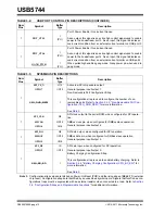
Note 1:
Configuration straps are identified by an underlined symbol name. Signals that function as configurations
traps must be augmented with an external resistor when connected to a load. Refer to
uration Straps and Programmable Functions"
for additional information.
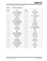
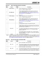
FIGURE 3-1:
56-VQFN PIN ASSIGNMENTS
Note: Exposed pad
( VSS
) on bottom of package must be connected to ground with a via field
.
(Connect exposed pad to ground with a via field
)
V S S
USB5744
5 6 -V QF N
( To p V i e w )
4
5
6
7
8
9
10
11
18
19
20
21
22
23
24
25
39
38
37
36
35
34
33
32
53
52
51
50
49
48
47
46
USB 3DN_RXDM1
USB3DN_RXDP1
USB2 DN_DP2/PRT_DIS_P2
USB2DN_ DM2/PRT_DIS_M2
USB3DN_TXDP2
USB3DN_ TXDM2
VDD12
USB3DN_RXDP2
SPI_CE_N/CFG_NON_REM
SPI_DI/CFG_BC_EN
SPI_CLK/SMCLK
VDD12
VDD33
USB3DN_RXDM4
USB
3
UP
_
R
XDP
VDD1
2
VD
D1
2
USB
3
UP
_
R
XDM
USB
3
UP
_
T
X
D
M
USB
2
D
N
_
D
M
4
/P
RT
_
D
IS_
M
4
USB
3
D
N
_
R
XDP
3
USB
3
DN_
T
XDP
3
USB
2
D
N
_
D
M
3
/P
RT
_
D
IS_
M
3
USB
2
DN_
DP
3
/P
R
T
_
D
IS_
P
3
VDD
3
3
USB
2
UP
_
D
P
VBUS_DET
USB
2
UP
_
D
M
USB
3
DN_
T
XDP
4
USB
3
UP
_
T
X
D
P
VDD
1
2
SPI_DO/SMDAT
45
44
55
54
2
3
12
13
16
17
26
27
31
30
41
40
USB
3
DN_
T
XDM
3
US
B
3
D
N
_
R
XDM
3
USB
2
DN_
DP
4
/P
R
T
_
D
IS_
P
4
USB
3
DN_
T
XDM
4
VDD12
USB3DN_ TXDM1
USB3DN_TXDP1
USB2DN_ DM1/PRT_DIS_M1
A
TES
T
XT
A
L
O
XT
A
L
I/
CL
K
_
IN
VD
D3
3
PRT_CTL1
PRT_CTL2
PRT_CTL3
PRT_CTL4/GANG_PWR
1
USB2 DN_DP1/PRT_DIS_P1
14
USB 3DN_RXDM2
15
VDD
1
2
VDD
1
2
28
29
USB3DN_RXDP4
RESET_N
42
43
VD
D3
3
RB
IA
S
56

