background image

7

Microframe Corporation

Series 3400 - Coaster Call Paging System

1  INSTALLING THE TRANSMITTER

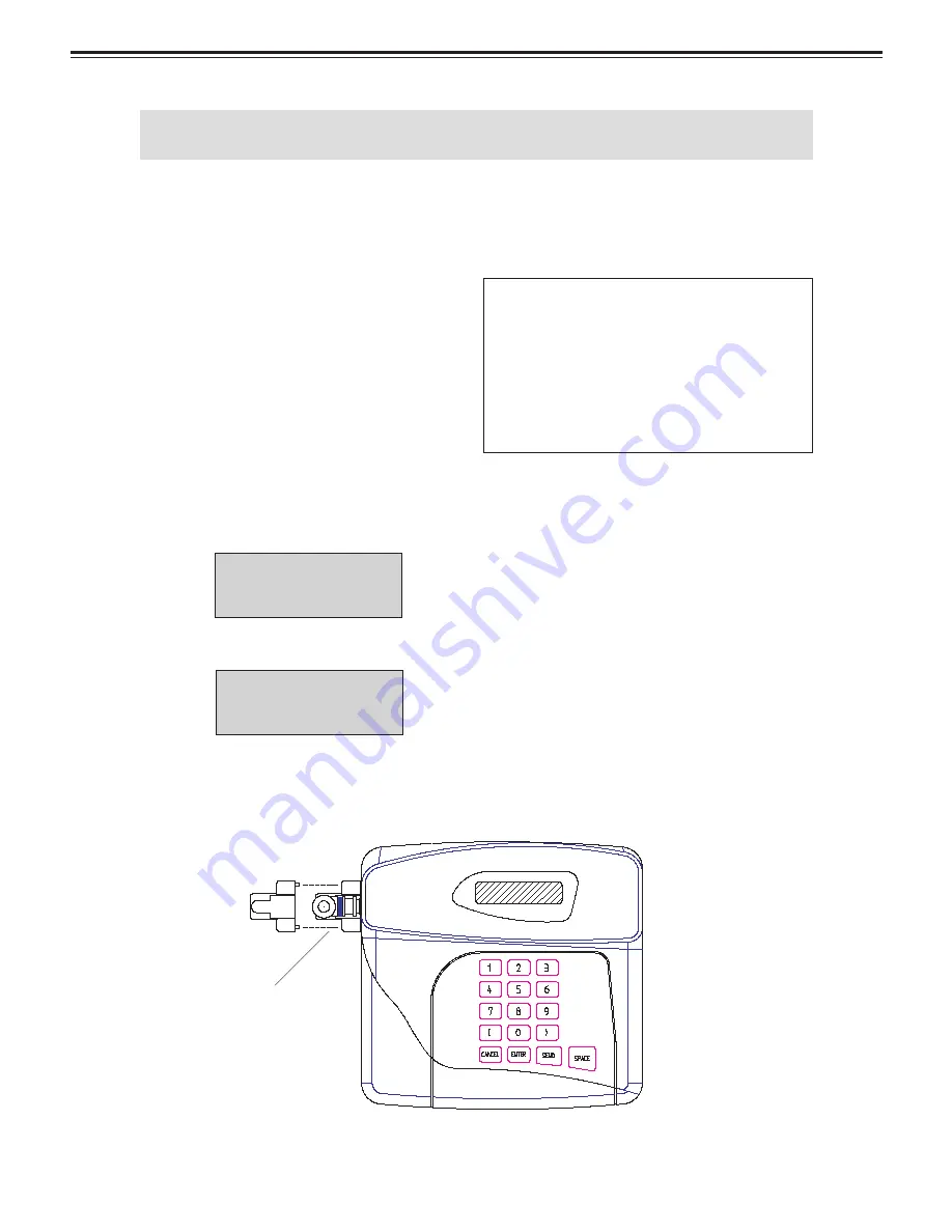
Figure 1: Connecting the Antenna and Locking Cover

1.1 CONNECTING THE ANTENNA

Connect the 90 degree antenna to the BNC 

connector located at the side of the transmit-
ter. Slide the plastic cover over the connector, 
engaging the two lugs into the corresponding 
recesses in the side of the case. This will main-
tain the antenna in an upright position, which 
is important for optimizing the range of the 
transmitter (See Figure 1). 

1.2 CONNECTING POWER SUPPLY

Connect the power supply to the power 

socket located at the right-hand rear corner of 
the base station (See Figure 2).

Plug the power supply into a convenient wall 

socket and turn on the power.  When the unit 
is fi rst powered up, the system will display the 
following screen for a few seconds:

  DATAPAGE

  LITE


Followed by:

  PAGER: (1-9999).

                  >

The fl ashing cursor invites you to enter a 

pager number (this can be any number between 
1 and 9,999) after which you must press SEND 
to transmit a page. See "OPERATION" (page 
9) for further transmitting procedures.

IMPORTANT NOTE:

 Use only the power supply provided with 
your system!  The use of non-approved 
power supplies will invalidate all war-
ranty and service. We also recommend 
using a surge suppressor for protection. 
Power surges are not covered under the 
warranty.  

1.3 PRECAUTIONS

Avoid mounting the transmitter in the im-

mediate vicinity of telephones, exchanges or 
computer equipment. A few feet can make the 
world of difference in avoiding interference 
from the radio frequency generated by the 
transmitter.

The performance of your system will be af-

fected by: foil backed wallboard, metal mesh, 
wire-reinforced glass, metal sheeting, large 
mirrors, suspended ceilings, elevator shafts, 
etc. These can all refl ect and thereby reduce the 
signaling capability of the transmitter. A little 
forethought prior to installation, coupled with a 
few tests, can normally avoid most problems.

BNC Connector

Summary of Contents for 3400 Series

Page 1: ...Microframe Corporation Series 3400 Coaster Call Paging System Operating Manual B3400 7012 B3400 7012 ...

Page 2: ...INSTALLATION SPECIFICATION GUIDE ITEM NO A3400 7012 REVISION DATE 11 09 Microframe Corporation 604 S 12th Street Broken Arrow OK 74012 Tel 918 258 4839 Toll Free 1 800 635 3811 Website www microframecorp com E mail support microframecorp com ...

Page 3: ... microframecorp com Safety Do not install substitute parts or perform any modification to the product without first contacting Microframe Warning All power transformers line cords and electrical equipment should be kept out of the reach of children and away from water Life Support Policy Microframe s products are not autho rizedforuseascomponentsinlifesupport devices or systems without the express...

Page 4: ...UP COASTERS 8 3 OPERATION 9 3 1 HANDING OUT COASTERS 9 3 2 PAGING THE GUEST 9 3 3 OUT OF RANGE FEATURE 9 3 4 CHANGING THE ALERT MODE 9 3 5 AUTO LOCATE FEATURE 9 4 SYSTEM OVERVIEW 10 4 1 DESCRIPTION 10 4 2 RANGE EXPANSION 10 4 3 IMPORTANT INFORMATION 10 4 4 SAFETY INFORMATION 10 4 5 CARING FOR TRANSMITTER 10 4 6 LIABILITY 10 4 7 WARRANTY INVALIDATION 10 4 8 SERVICE INFORMATION 10 MINI DIPOLE ANTENN...

Page 5: ... out of range the moment they step out by continuously playing a melody until the mo ment they step back in This feature helps reduce the number of missed pages as well as accidental coaster walk outs Coasters are rechargeable and will last approximately 3 5 years before replacement of the battery is necessary Operation The transmitter and charging base simply plug into an outlet using the power a...

Page 6: ... The flashing cursor invites you to enter a pagernumber thiscanbeanynumberbetween 1 and 9 999 after which you must press SEND to transmit a page See OPERATION page 9 for further transmitting procedures IMPORTANT NOTE Use only the power supply provided with your system The use of non approved power supplies will invalidate all war ranty and service We also recommend using a surge suppressor for pro...

Page 7: ...rical cord into a standard 110 outlet 2 2 SETTING UP COASTERS Stack the coasters on the black charging base The coaster number will always face the front and the red charge indicator light will be on the left We recommend that you do not stack coasters more than 15 high as damage to the charger base may occur A red light should appear on each coaster to indicate proper charging The supplied 12v AC...

Page 8: ...tter After 30 seconds all the coasters will play a melody since they are not receiv ing a signal from the transmitter Return all the coasters to the charging base or plug the power supply back in The coasters are ready to receive a page with the Out of Range feature turned on Follow the same procedure as above to turn off the Out of Range feature using the code 9393 instead of 9494 3 OPERATION 3 4...

Page 9: ...led and used according to generalsafetypractices Thefollowingrequire ments should be observed at all times Do NOT subject this equipment to Mechanical shock Excessive humidity or moisture Extremes of temperature Corrosive liquids This equipment is designed for indoor use unless expressly stated otherwise and must not be used in classified Hazardous Areas including areas containing explosive or fla...

Page 10: ...towards the ground Avoid mounting the dipole on or near to any metal girders pilars or other metallic obstructions The dipole should preferably be mounted at a height which avoids potential snagging with any moveable objects that might be used in the vicinity e g ladders Ensure that the bracket is firmly bolted to a solid suf ace and that the feeder cable is adequately clamped along it s entire ru...

Page 11: ...rporation Series 3400 Coaster Call Paging System Microframe Corporation 604 S 12th Street Broken Arrow OK 74012 Tel 918 258 4839 Toll Free 1 800 635 3811 Website www microframecorp com E mail support microframecorp com ...

Reviews: