microHAM © 2016 All rights reserved
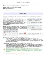
PORTS TAB
Once the virtual ports have been created they must be associated with a specific device channel (e.g.,
Control, CW, PTT, etc.). These assignments should correspond to settings of the application software and
must be configured first in Router then in the application (e.g., logging program, MMTTY, STREAM, etc.).
Proper assignment of the virtual COM ports
is vital for intergration with loggers.
Read the
following information carefully.
USB Interface II has four functions with indication of the state and settings applied by the host application
●
Radio Control (uses RxD and TxD)
●
CW (uses DTR)
●
PTT (uses RTS)
●
Squelch (uses CTS)
General note: Do not assign virtual ports for a function which is not used by your application. It is
unnecessary and only consumes resources.
RADIO PORT
The control channel is used by the host application to control transceiver frequency, mode, T/R switching
and many other parameters. The application communicates with the radio using a serial protocol. Most
modern radios implement some form of serial control but almost every radio implementation is different.
The amount of radio control depends on the particular application and radio.
TIP: The COM port number assigned in Router MUST match the port number assigned in the host
application. First configure the virtual COM ports in Router then configure the application.
NOTE: The USB Interface III does not use handshake on radio port. Configure DTR and RTS settings in your
application program (logger) to OFF. DO NOT select “Handshake.”
TIP: Disable AUTOBAUD in Icom transceivers. Set the radio, Router, and application software to
operate at 9600 or 19200 baud.
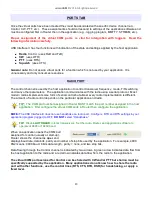
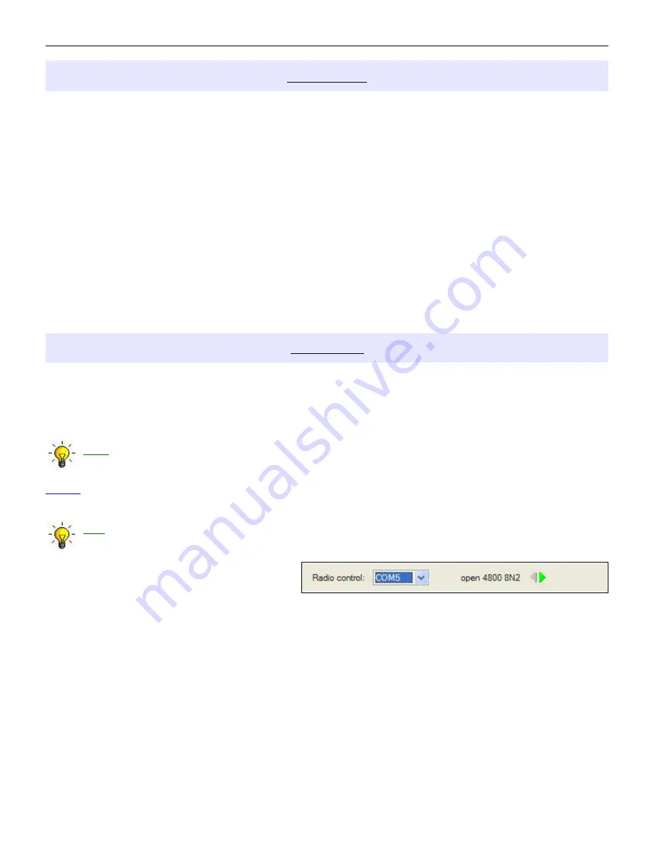
When an application opens the COM port
assigned for control (usually at start-up),
Router shows the channel as open and
displays baud rate, data bits, parity and number of stop bits used by the applicaiton. For example, 4800
8N2 means: 4800 baud, 8 bits data length, parity = none, and two stop bits.
Data flowing through the Control channel is indicated by two arrows. A green arrow indicates data flow from
the host application to the radio and a red arrow indicates data flow from the radio to the application.
The virtual COM port assigned for Control can be shared with CW and/or PTT but sharing must be
specifically supported by the application. Many applications do not know how to share the radio
port with other functions, use the control lines (RTS, CTS, DTR, DSR) for handshaking, or apply a
fixed level.
13


