© Microhard Systems Inc.
97
4.0 Configuration
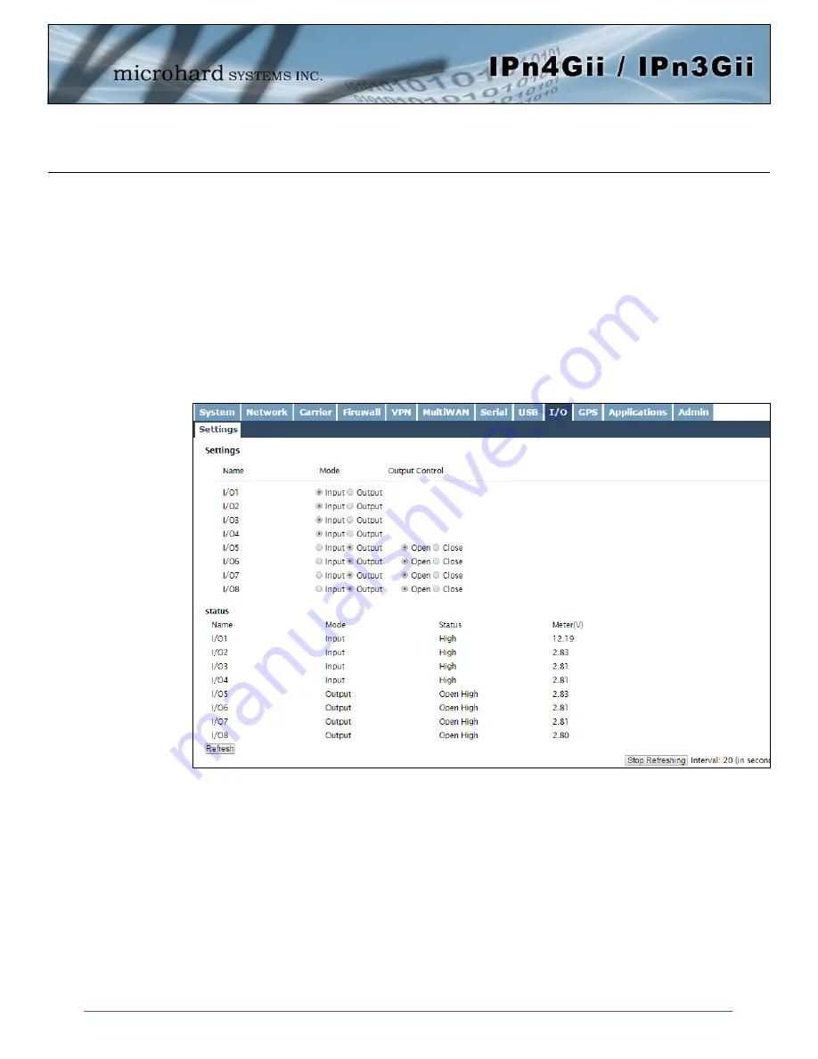
Image 4-9-1: I/O Settings
4.9 I/O
4.9.1 I/O > Settings
The IPnXGii has 8 programmable I/O’s, which can be used with various alarms and sensors for monitoring,
telling the modem when certain events have occurred, such as an intrusion alarm on a door, etc. Any of the
I/O’s can also be programmed to operate as a output, that can be used to drive external relays to remotely
control equipment and devices. The I/O pins are available on the back connector shared with the input
power (1&2), as well as the 10 pin connector (I/O 3 - 8).
The Status of the I/O’s can be read, and in the case of outputs, can be operated in the WebUI. Alerts can
be setup to send SMS Messages if I/O Status changes, as well, SMS control messages can be sent to the
device to trigger events. SNMP and/or Modbus can be used to poll for the status, or set controls. See the
appropriate sections of the manual for more information.
Settings
The Settings menu is used to configure a I/O as either a Input or an Output. If configured as an output, the
user can also set the output as open or closed. The output pin on the IPnXGii can be used to provide
output signals, which can be used to drive an external relay to control an external device. See
Table 4-8-1
for I/O specifications.
Status
The Status section will display the current state and measured voltage (Meter) of any I/O’s configured as
inputs. The WebUI will also display the current state of each control output.


