background image

Follow these steps for connecting and disconnecting RF cables to the unit. Ground the unit, make all RF con

-

nections and terminate all unused RF connections before applying DC Power.

Connect RF cables as shown in the 

System Connection Diagram

Sequence to connect:

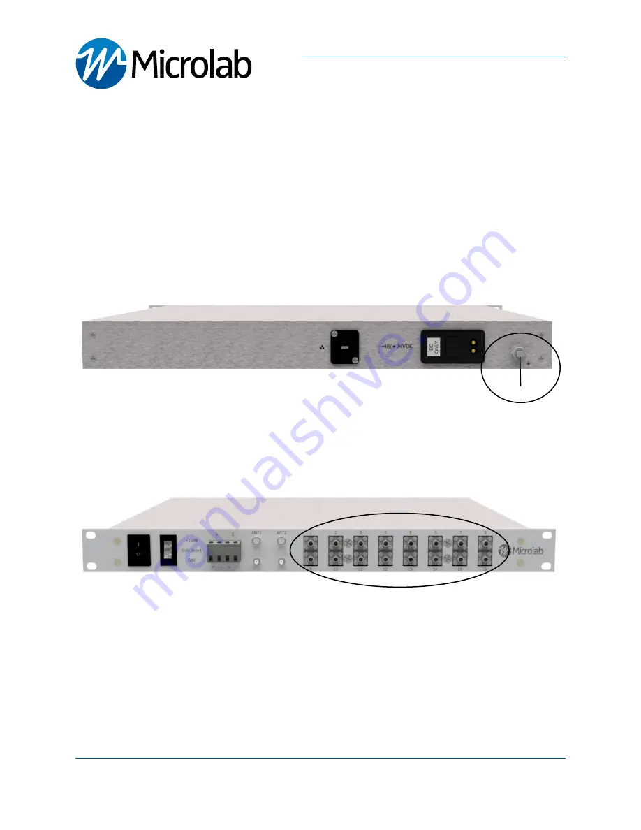
1. Connect System Ground.
 

- The remote unit comes with a .25-20FLANGENUT grounding lug. A grounding wire of suitable  


   gauge must be used to ground to a common bus bar in the Telecom room according to local and


   building regulations.

2. Connect each RF Output (

Ports 1 through 16) 

to each eNode B or BBU GPS inputs


- Apply appropriete torque to SMA connectors


- It is recommended that all unsued RF outputs MUST be terminated with a 50Ω load

  See 

Microlab 

TA-1MF

 terminations

Microlab, A Wireless Telecom Group Company, 25 Eastmans Road, Parsippany, NJ 07054

Tel: (973) 386-9696 • sales@microlabtech.com • www.microlabtech.com • Fax: (973) 386-9191

Connections RF and Ground

GPSS216 Quick Start Guide

Lossless GPS Signal Splitter, 16 RF Ouput

page 3

Ground Lug

SMA RF Outputs

Summary of Contents for GPSS216

Page 1: ...Microlab A Wireless Telecom Group Company 25 Eastmans Road Parsippany NJ 07054 Tel 973 386 9696 sales microlabtech com www microlabtech com Fax 973 386 9191 GPSS216 Quick Start Guide ...

Page 2: ...up to 32 remote units located where the GPS signals are not readily available The GPS signal quality is actively monitored by this system and can be combined other Microlab Lossless GPS Signal Splitters to expand the RF outputs It offers 16 channel and 32 channel options Gain Switch Introduction Model Description GPSS216 Lossless GPS signal splitter 2RF inputs 16 RF output 1RU GPSS232 Lossless GPS...

Page 3: ...SS216 requires DC Power 48 24VDC The DC interface mates with the included power cable model PSM 129 Mount the GPSS216 Head End Unit in close proximity to the eNode B or BBU to minimize cable lengths Install the rack mount GPSS216 on an EIA standard 19 rack using standard hardware and practices GPSS216 Quick Start Guide Lossless GPS Signal Splitter 16 RF Ouput page 2 Up to 16 BBU GPSS216 16 RF outp...

Page 4: ... to a common bus bar in the Telecom room according to local and building regulations 2 Connect each RF Output Ports 1 through 16 to each eNode B or BBU GPS inputs Apply appropriete torque to SMA connectors It is recommended that all unsued RF outputs MUST be terminated with a 50Ω load See Microlab TA 1MF terminations Microlab A Wireless Telecom Group Company 25 Eastmans Road Parsippany NJ 07054 Te...

Page 5: ...perator approved GPS Antennas Apply appropriete torque to SMA connectors Microlab A Wireless Telecom Group Company 25 Eastmans Road Parsippany NJ 07054 Tel 973 386 9696 sales microlabtech com www microlabtech com Fax 973 386 9191 Connections RF and Ground Continued GPSS216 Quick Start Guide Lossless GPS Signal Splitter 16 RF Ouput page 4 ANT2 ANT1 Note DC supply to antenna ports is 5V nominal 100m...

Page 6: ... Solid GREEN Antenna LEDs indicate normal operation See LED Antenna Verification section for details Off Status LEDs indicate that power supply is not functioning or not connected Microlab A Wireless Telecom Group Company 25 Eastmans Road Parsippany NJ 07054 Tel 973 386 9696 sales microlabtech com www microlabtech com Fax 973 386 9191 Connecting Power Connect DC Positive and Negative terminals as ...

Page 7: ...over to secondary when primary goes into abnormal condition Microlab A Wireless Telecom Group Company 25 Eastmans Road Parsippany NJ 07054 Tel 973 386 9696 sales microlabtech com www microlabtech com Fax 973 386 9191 LED Antenna Verification GPSS216 Quick Start Guide Lossless GPS Signal Splitter 16 RF Ouput page 6 Antenna Status GPS Lock Status LED Status Normal GPS Lock Solid GREEN Fault GPS No L...

Page 8: ...ed outputs are terminated with 50Ω loads 2 Set Gain Select switch to the 10dB position maximum gain 3 Verify signal level at the ouput is sufficient for the next system stage Gain Select GPSS216 Quick Start Guide Lossless GPS Signal Splitter 16 RF Ouput page 7 Sequence to Disconnect 1 Turn Down gain Set Gain Select switch to the 0dB position 2 Switch OFF the unit 3 Remove Disconnect DC power to th...

Page 9: ...ed environment European regulations vary by country Consult local authorities for additional details Contact Microlab Active Solutions To contact Microlab visit our website at www microlabtech com or send email to sales microlabtech com For operating assistance in the USA call 973 386 9696 Safety Information To avoid possible electric shock or personal injury the following general safety precautio...

Page 10: ...m Group Company 25 Eastmans Road Parsippany NJ 07054 Tel 973 386 9696 sales microlabtech com www microlabtech com Fax 973 386 9191 Page Intentionally Left Blank GPSS216 Quick Start Guide Lossless GPS Signal Splitter 16 RF Ouput ...

Reviews: