background image


Rotary Microtome HM 325 

MICROM International GmbH 
Robert-Bosch-Str. 49 
 
D- 69190 Walldorf 


387821 - English 


3 OPERATING 

INSTRUCTIONS 


3-1 

SETTING UP THE MICROTOME 


Note:  

The kind of the used examination 
materials and all special conditions for 
their processing, pre-treatment and, if 

necessary, storage as well as instrument controls 
for correct and safe operation is in the 
responsibility of the operator. 
The operator is also responsible for special 
equipment and materials and/or reagents for the 
operation of the instrument. 
 

• 

Cut through the bands around the carton. 

• 

Open the carton. 

• 

Remove the accessories. 

• 

On the lower rear side of the instrument, there 

is a recessed grip to lift or carry the 
microtome. 

• 

Lift the microtome out of the carton. 


Note:  

Do not use the handwheel handles to 
lift or carry the instrument. 


• 

Place the microtome on a stable and vibration 

free table, as sectioning can be influenced by 
nearby instruments which generate vibrations. 

• 

Handwheel and coarse feed wheel must be 

free and accessible in a comfortable way. 

• 

Remove the separately packed section waste 

tray and install it at the base plate from the 
front side. 


• 

In the rear part of the instrument, there are 

sliding feet for an easy moving of the 
microtome.  

• 

Slightly lift the base at the front end only and 

slide the microtome. 


Summary of Contents for HM 325

Page 1: ...Rotary Microtome HM 325 MICROM International GmbH Robert Bosch Str 49 69190 Walldorf 387821 English ROTARY MICROTOME HM 325 INSTRUCTION MANUAL ...

Page 2: ...Rotary Microtome HM 325 MICROM International GmbH Robert Bosch Str 49 D 69190 Walldorf 387821 English ...

Page 3: ...GmbH No other warranty is expressed or implied Unauthorized modification or repair by third party persons will void the warranty The warranty will expire in case of improper or wrong use of the instrument and in case the warning and precautionary messages are not observed MICROM International GmbH is not liable for any occurring damage Errors and omissions excepted Subject to amendment and improve...

Page 4: ...tees would then be null and void Only skilled or specially trained personnel must operate the microtome i e clamping the specimen trimming and first cuts sectioning and transferring sections onto a slide The listed and marked safety measures as well as the regulations and hygiene measures of your respective lab must strictly be observed MICROM serial number Please check the MICROM Ser No on the ty...

Page 5: ...tional 2 3 Technical data Rotary Microtome HM 325 PART 3 OPERATING INSTRUCTIONS 3 1 Setting up the microtome 3 2 Cutting movement and retraction 3 3 Locking and unlocking the handwheel 3 4 Section thickness setting 3 5 Section counter 3 6 Specimen feed 3 6 1 Trimming and first cuts 3 6 3 Fine feed 3 7 Acoustic signal for the front end position of the specimen movement 3 8 Adapters for specimen cla...

Page 6: ...rier ER 3 10 2 Disposable blade carrier E 3 10 3 Knife carrier C 3 10 4 Readjusting the knife carriers 3 11 Section waste tray 3 12 Large field magnifier PART 4 WORKING WITH THE MICROTOME 4 1 Sectioning instructions 4 2 How to avoid malfunctions 4 3 Possible source of errors cause and removal PART 5 MAINTENANCE AND CARE 5 1 Cleaning and care 5 2 Maintenance 5 3 Replacement work PART 6 CONDITIONS F...

Page 7: ...een registered with the German authority as Microtomes under the EDMA classification code 23 06 02 The designated product complies with the laid down regulation DIRECTIVE 98 79 EC OF THE EUROPEAN PARLIAMENT AND OF THE COUNCIL of 27 October 1998 on in vitro diagnostic medical devices The designated product complies with the EC regulations by strictly observing the following norms DIN EN ISO 14971 2...

Page 8: ...Rotary Microtome HM 325 MICROM International GmbH Robert Bosch Str 49 D 69190 Walldorf 387821 English Hans Heid Walldorf 16 June 2005 Managing Director ...

Page 9: ...res to prevent damage to equipment For a long lifetime of the equipment please observe these instructions carefully Caution general danger spot The instruction manual must strictly be observed whenever this symbol is visible on the instrument Hazard of hand injuries Due to moving parts in connection also with the microtome knife a danger area arises which might lead to hand injuries in case of non...

Page 10: ...If possible the specimen should be clamped in before the knife is inserted into the knife holder Before changing the knife holder always remove blade or knife Unused knives should always be kept in a knife case Never place the knife with the cutting edge upwards Never try to catch a dropping knife Never check the sharpness of the cutting edge with your fingers The cutting edge is extremely sharp H...

Page 11: ...tamination media their use dilution and effective range of application can be read in the Laboratory Biosafety Manual 1984 of the World Health Organization WASTE DISPOSAL All debris waste as well as infectious and radioactive contaminated material from operation must be disposed of in accordance with the respective regulations of the lab Section waste must be disposed of according to the respectiv...

Page 12: ...d for paraffin sectioning in biology medicine and industry Only skilled or specially trained personnel must operated the microtome i e clamping the specimen trimming sectioning and taking off the sections from the instrument The listed and marked safety measures as well as the regulations of your respective lab must be strictly observed Note This instruction manual is part of the product Keep it a...

Page 13: ... µm up to 60 µm For the protection of knife and specimen the instrument retracts the specimen at the end of the cut Forward and backward travel is carried out by the coarse feed wheel This way specimen and knife edge distance can be adjusted quickly An additional trimming function with two defined steps permits the fine adjustment up to the first cuts and results in larger section thicknesses when...

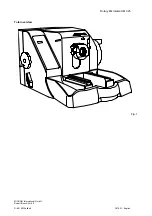
Page 14: ...Rotary Microtome HM 325 MICROM International GmbH Robert Bosch Str 49 D 69190 Walldorf 387821 English Total overview Fig 1 ...

Page 15: ...ONAL 2 2 2 1 KNIFE CARRIER Cat No Standard knife carrier N 705670 Disposable blade carrier E 705640 Disposable blade carrier ER 705650 2 2 2 2 SPECIMEN CLAMPS Standard specimen clamp 715010 Universal cassette clamp 715020 Adjustable universal cassette clamp 716130 Foil clamp 715030 Sandwich supporting material 176010 Insert for round specimens Ø 6 mm 715070 Insert for round specimens Ø 15 mm 71508...

Page 16: ...0 755210 Adapter for Stemi 2000 532090 KL 1500 with ring illumination 230 V 50 60 Hz 760280 120 V 50 60 Hz 760290 2 2 2 4 MICROTOME KNIVES Steel knives type c 12 cm 152010 16 cm 152020 18 5 cm 152270 22 cm 152030 Steel knives type d 12 cm 152060 16 cm 152070 22 cm 152080 Tungsten carbide knive 16 cm d 152120 Knife cases 12 cm 152220 16 cm 152230 18 5 cm 152280 22 cm 152240 Disposable blades for pa...

Page 17: ...English 2 2 2 5 ADDITIONAL ACCESSORIES Fast freezing unit K 34 100 V 50 60 Hz 115 V 60 Hz 230 V 50 Hz 240 V 50 Hz Section transfer system STS 100 V 50 60 Hz 115 V 60 Hz 230 V 50 Hz 240 V 50 Hz Lubricating oil 100 ml 350110 Lubricating oil 250 ml 350120 Paraffin repellent PARA GARD 100 ml 350170 ...

Page 18: ...ax 64 mm Trimming stage 1 10 µm Trimming stage 2 30 µm Section counter Battery powered four digit LC display with reset 4 digit Specimen size Standard 55 x 50 mm Specimen orientation x and y axes universal 8 z axis up to 360 Cutting drive manual by means of handwheel right side Coarse feed manual by means of handwheel left side Storage temperature range 20 C up to 50 C Operating conditions 5 C to ...

Page 19: ...ound the carton Open the carton Remove the accessories On the lower rear side of the instrument there is a recessed grip to lift or carry the microtome Lift the microtome out of the carton Note Do not use the handwheel handles to lift or carry the instrument Place the microtome on a stable and vibration free table as sectioning can be influenced by nearby instruments which generate vibrations Hand...

Page 20: ...he instrument The section waste tray can be pulled out of its proper position Before starting section instrument knife carrier and section waste tray should be treated with a commercially available paraffin repellent Note This medium considerable reduces the adhesive force of paraffin sections on the individual parts see part 2 2 2 5 optional accessories ...

Page 21: ...vel the specimen is retracted R If desired the function retraction can be turned off 3 3 LOCKING AND UNLOCKING THE HANDWHEEL The handwheel is integrated into the housing The position of the handle corresponds to the vertical position of the specimen Turn the lever downwards in the direction of the arrow to loosen the handwheel lock Turn the lever upwards to lock the handwheel The handwheel can be ...

Page 22: ...uation up to 2 µm 0 5 µm from 2 µm to 10 µm 1 µm from 10 µm to 20 µm 2 µm from 20 µm to 60 µm 5 µm Warning When the setting is changed from larger to smaller section thicknesses the next section will still be done at the previous value if the setting was changed in the upper position of the cutting process Therefore when changing the section thickness always use the lower position of the cutting p...

Page 23: ...istance can be noticed and when the handwheel for the cutting drive is activated an acoustic signal can be heard Warning Do not continue to advance the specimen after reaching the front end position with the coarse feed wheel or the handwheel This will damage the mechanical parts Warning When turning the coarse feed wheel take note that the specimen and knife edge do not get in contact with each o...

Page 24: ...ted if the specimen is not in the upper position After the specimen is adjusted approximately to the knife edge turn the trimming lever fig 7 1 to further advance the specimen gradually for the first cuts 3 6 3 FINE FEED For the fine feed in µm steps turn the turning knob fig 8 8 on the right side of the instrument housing to the right or left side The setting can then be read in the window fig 8 ...

Page 25: ...nal sounds during each rotation of the handwheel Warning When the signal sounds a feed range of no more than 1000 µm is available to finish sectioning To avoid damaging mechanical parts set back the specimen holder by means of the coarse feed wheel before starting the next sectioning series Note Sections should be cut in the back third of the horizontal specimen movement because the mechanical sta...

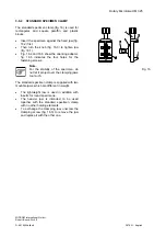
Page 26: ...fe To bring the specimen into the desired position turn the clamping lever fig 10 1 towards the front This will loosen the specimen clamp and a rotation of 360 on the cylinder axis Z axis is possible With the two orienting screws fig 10 2 the specimen clamp can be oriented 8 in each direction on the X axis and Y axis After having oriented the specimen turn the lever fig 10 1 upwards to fix the spe...

Page 27: ...s the clamping lever fig 11 1 downwards and pull it sideways Now the specimen clamp can be pulled out to the front and can be replaced with another specimen clamping system Insert the new specimen clamp into the cylinder head so that the clamping lever can be put through the hole of the adapter from the right side all the way through Then align the specimen clamp by means of the orienting screws f...

Page 28: ...at the specimen clamp cannot be clamped The clamping lever fig 12 1 should be in an almost upright position To determine the clamping position of the clamping lever adjust the inner screw fig 13 1 on the backside of the orienting adapter by means of an Allen key size 3 mm Turn the Allen key in a clockwise direction if no clamping was achieved at all or if the clamping position of the clamping leve...

Page 29: ...sents a quick change system To insert or remove the cassette from between the fixed fig 14 1 and movable fig 14 2 jaws pull the lever fig 14 3 to the front in the direction of the arrow Note To achieve optimal clamping keep the locating surface of the cassette free of paraffin 3 9 2 UNIVERSAL CASSETTE CLAMP ADJUSTABLE To insert and or remove cassettes between the fixed jaw fig 15 1 and the movable...

Page 30: ...rienting adapter fig 16 6 indicates the four holes for the fastening screws Note For the stability of the specimen do not let it project over the clamping jaws too much The standard specimen clamp is supplied with two movable jaws which are different in weight The lightweight jaw is used in addition with inserts for round specimens The heavier jaw is intended to be used together with the standard ...

Page 31: ...d into the standard specimen clamp The pin fig 17 3 which fits into the lower clamping jaws fig 16 1 positions the insert precisely The two springs fig 17 4 make it easy to remove the specimen from the inserts fig 17 1 and 17 2 To fasten the V distance piece fig 17 C on the fixed jaw fig 16 2 of the standard specimen clamp the clamping screw fig 16 3 must be unscrewed from the spindle Pull the spi...

Page 32: ...r its position can be changed Turn the three clamping screws fig 18 5 to clamp the specimen tightly When using an orienting adapter with the instrument first insert the enclosed graduated ring into the orienting adapter by means of the pin With the graduated ring the orientation in X Y direction is annulled However it is possible to turn in Z axis 60 in either direction Then insert the foil clamp ...

Page 33: ...blades Insert the blade into the slot behind the clamping plate fig 19 5 For this turn the clamping lever fig 19 7 towards the front Swing the bracket with scale fig 19 4 to the front Loosen the clamping lever fig 19 7 and if necessary slightly push the lower part of the clamping plate fig 19 5 as well Insert the blade on the rail fig 19 3 and push it from the side to the middle Afterwards return ...

Page 34: ...spective requirements of the tissue to be sectioned Loosen the clamping lever fig 19 8 on the right side of the knife carrier and move the upper part fig 19 9 of the knife carrier on the base fig 19 1 The adjusted clearance angle can be read on the scale Then turn the clamping lever fig 19 8 upwards to lock in the new clearance angle The clamping lever for the angle adjustment can be pulled off af...

Page 35: ...tion The bracket fig 20 4 is provided with a scale After loosening the clamping lever fig 20 7 and after having moved the bracket fig 20 4 upwards move the blade together with clamping plate fig 20 5 according to the scale by means of the knife guard to the left or right side This way the entire cutting length of the blade can be used Then press the clamping lever fig 20 7 upwards The levers fig 2...

Page 36: ...e can optimally be used The clamping lever for the angle adjustment can be pulled off after a correct angle setting to avoid that the angle is reset unintendedly Moving the knife carrier on the console Loosen the clamping lever fig 20 6 on the left side of the knife carrier to move the carrier forwards or backwards on the dovetail guide This allows a rough adjustment of the knife to the specimen P...

Page 37: ...learance angle adjustment The clearance angle between cutting edge and specimen can be shifted and adjusted to the requirements of the tissue to be sectioned Loosen the clamping lever fig 21 4 on the right side of the knife carrier and move the upper part of the knife carrier fig 21 2 on the base fig 21 1 The adjusted clearance angle can be read on the side scale Then turn the clamping lever fig 2...

Page 38: ...ipped with two knife guards fig 21 7 which can be moved sideways These knife guards should be pushed together in the middle while adjusting knife or specimen This reduces the danger of injury considerably Central clamping plate The knife is clamped and stabilized in the cutting zone by the central clamping plate fig 21 8 exactly where the highest cutting forces are applied Two types of clamping pl...

Page 39: ...w a sufficient clamping the clamping can be adjusted as follows For this loosen the set screw fig 24 1 on the lower side of the knife carrier Insert a pin into one of the holes of the brass screw fig 24 2 and turn the brass screw When the clamping is to be strengthened turn the brass screw fig 24 2 to the right side When the clamping is to be loosened turn the brass screw to the left side Before i...

Page 40: ...821 English 3 11 SECTION WASTE TRAY WITH INTEGRATED ARM REST The section waste tray with integrated arm rest can easily be cleaned The section waste tray surrounds the knife carrier area and allows non tiring working with the microtome It can be easily removed to the front at any time Fig 25 ...

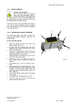
Page 41: ... instrument hood Remove the front plastic caps from the upper side of the housing If there are no drilled holes in the housing it must be replaced with a new one with drilled holes Fasten the peg fig 26 4 to the plate fig 26 6 with the screw fig 26 7 Carefully introduce the four sleeves fig 26 8 into the drilled holes with the screws fig 26 5 Warning Please note that the sleeves do not fall into t...

Page 42: ...orking with the sharp area of the cutting edge or have the knife resharpened For optimal sectioning front and back of the knife must be clean Especially paraffin waste must be removed thoroughly Setting the cutting angle Inclination of the knife in relation to the block surface Each microtome knife has a so called facet cut resulting from the fact that when producing a knife or when resharpening t...

Page 43: ...he knife might vibrate too much while sectioning The so called chatters appear on the block surface as well as on the sections These chatters are parallel stripes in relation to the knife edge having negative effects on the microscopical evaluation of sections Between these two limit cases the correct knife inclination must be determined A clearance angle between facet angle and block surface of a...

Page 44: ... sources of heat Tightening the clamping screws Tighten all clamping screws and clamping levers on the knife carrier specimen holder and specimen orientation Selection of the knife Carefully select the required knife material and profile Adjustment of the knife Take care to adjust the proper clearance angle of the knife 5 7 for glass knives For diamond knives ask the knife manufacturer Select a cl...

Page 45: ...il an optimal angle can be found Turn handwheel slower Chatter on sections Cutting speed too high Unfavourable clearance angle Insufficient clamping on specimen clamping and or knife carrier Turn handwheel slower Try clearance angle adjustments until an optimal angle can be found Check all screw and clamping connections on specimen clamping and knife carrier Tighten them if necessary No feed is ca...

Page 46: ...er especially the space where the knife carrier is installed Clean the consoles handwheel coarse feed wheel specimen clamping system specimen orientation as well as the base plate and housing Note Mild domestic cleaners can be used to clean the microtome Do not use aggressive cleaners or solvents as the paint and plastic parts can be affected Warning When getting in contact with cleaning agents or...

Page 47: ...This battery should be changed by a service technician after 5 years Service contract MICROM offers a service contract which guarantees that your instrument is always in perfect condition For more information please contact the nearest MICROM sales office Note We strongly recommend to not carry out repair by yourself All warranties and guarantees would then be null and void Repair work must only b...

Page 48: ...he below mentioned measures for transportation preparations In addition the conditions for storage and transportation as mentioned in part 2 3 must be observed during the entire transportation Biohazard Please also note the precautionary measures described in our safety precautions concerning biological hazards Measures for taking out of operating Lock the handwheel Remove knife or blade and store...

Page 49: ...de of the instrument During transportation do not carry the instrument on the handwheel handles Danger of being injured Pack the instrument into the original packing as it offers best pre conditions for transportation without damage Note If the original packing is no longer available please contact your local MICROM representation 6 2 DISPOSAL OF THE INSTRUMENT AFTER FINAL SHUTDOWN After the final...

Reviews: