Micromeritics SediGraph III 5120, Installation Instructions And Checklist
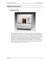
The Micromeritics SediGraph III 5120 is a high-quality instrument for particle size analysis. For installation, follow the detailed Installation Instructions And Checklist provided in the manual. You can download the manual for free from 88.208.23.73:8080 to ensure smooth operation and accurate results.
Share
Download


Reviews:
No comments
Related manuals for SediGraph III 5120

A series
Brand: Raymarine Pages: 464

701
Brand: 3M Pages: 8

M Series
Brand: ZOLL Pages: 3

MIC
Brand: Halyard Pages: 88

HPX
Brand: Keller Pages: 12

D50
Brand: MacDon Pages: 49

D50
Brand: MacDon Pages: 49

D50
Brand: MacDon Pages: 4

GPP5000 Series
Brand: Zimmer Pages: 2

UC5
Brand: ZipRip Pages: 31

bionic power knee
Brand: Össur Pages: 2

BALANCE KNEE OM8
Brand: Össur Pages: 36

BALANCE FOOT J
Brand: Össur Pages: 37

REBOUND DIABETIC WALKER
Brand: Össur Pages: 63

UNITY
Brand: Össur Pages: 67

ECHODIA Babyscreen
Brand: Électronique du Mazet Pages: 65

STOMAMED COL-160
Brand: Orliman Pages: 12

2261998USBA1-XX
Brand: MMF POS Pages: 5


