background image

5 4

Installing a modular hard drive or floppy drive

Your computer will automatically recognize a hard disk or floppy
disk drive module when you install it into an appropriate bay
(see Chapter 1).  This helps you use your modular drives for
sharing or transferring data between two TransPort X

KE

notebooks.

Warning:

Always power down your notebook completely
before installing or removing a drive module.

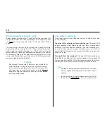
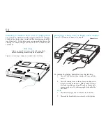
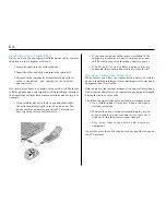
Figure 4-4: Inserting a floppy drive module into Left Bay.

Removing a hard drive or floppy drive module

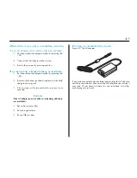
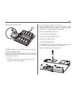
Figure 4-5: Removing a floppy drive module.

To remove the floppy disk drive from the left bay:

1

Turn off the system, then unplug it from outside
power.

2

Turn the computer over, then place your fingers in
the groove on the disk drive.  Slide back the release
latch and simultaneously pull firmly on the module
grooves as shown.  Once disengaged, it should slide
out easily.

Note:

1.

The modular floppy drive works only in the left bay.

2.

The modular hard disk drive works only in the right bay.

Release Latch

Summary of Contents for TRANSPORT XKE

Page 1: ...2 TRANSPORT XKE MAS001412 02 ...

Page 2: ...ument is for reference only All installation of internal optional devices or equipment including third party optional devices or equipment should be performed by an experienced and knowledgeable technician All servicing or upgrading of original or optional devices or equipment should also be performed by an experienced and knowledgeable technician 2 UNAUTHORIZED INSTALLATION SERVICING OR UPGRADING...

Page 3: ...re using a new battery pack 35 Inserting and removing a battery pack 36 Running on battery power 37 Recharging the battery pack s 37 Recharging two battery packs 37 Extra battery pack 37 Discharging two battery packs 38 Checking a non installed battery 38 Warm swapping a battery pack 39 Low battery warnings 39 What to do if you get a low battery warning 40 Running on external AC power 40 3 Hardwar...

Page 4: ...system s internal hardware This will help you understand your system s internal features set security options and control how your machine uses power Chapter 4 Installing Accessories shows how you can add more memory remove the internal hard drive and add or remove the modular drives Chapter 5 System Software Options describes some of the additional software that Micron has installed on your Windo...

Page 5: ...panel the keyboard with its numeric keypad and several interior features The rest of this chapter will describe what you see when you examine your TransPort XKE Do I have everything The packing slip is one of the last items sealed into your computer box It lists everything we shipped to you As you unpack the box check the contents against the packing slip If an item is listed on your packing slip ...

Page 6: ...Port Replicator normally Micron has loaded and tested the operating system on your hard drive You can skip the installation of the operating system and system drivers If you ever need to reload your operating system and or system drivers please refer to your Microsoft operating system manual What s in the box Keep the box It s a good idea to keep your TransPort s box and packing materials That way...

Page 7: ...enever you decide to pull over for roadside computing choose a clean comfortable work area for your system When traveling your system operates on an intelligent lithium ion battery pack Before you run your system for the first time on battery power removethebatteryfromitspackageandinstallitinthesystem then recharge the battery fully This prepares your lithium ion battery pack for maximum service C...

Page 8: ...MIDI device Custom designed heat dispersion helps keep your unit running coolly Interior fan cooling is silent efficient and more reliable System features The TransPort XKE notebook computer contains sophisticated features made possible only by the latest advances in computer hardware and software The standard configurations include up to a 266 MHz Intel PentiumprocessorwithMMXtechnology a12 1 or1...

Page 9: ...on bays and an infrared port To open the display panel Turn the front of the computer toward you Slide the front latch to the right then lift the display panel with both hands Tilt the display panel to a comfortable viewing angle Left FlexOpt Expansion Bay Holds either a floppy disk drive or lithium ion battery Right FlexOpt Expansion Bay Holds a CD ROM drive a battery or an extra hard drive Front...

Page 10: ... is OFF so howling will not occur However sometimes a software application is shut downwiththemicrophoneoutputsettingleftON When using such applications be sure to switch the microphone output setting to OFF after use Countermeasures If the Windows 95 desktop is displayed set the volume of the microphone output to minimum or off using the software volume control If any other screen is displayed pr...

Page 11: ...various controls and switches on the CD ROM drive The controls on the front of the CD ROM drive are functional whenever a pair of head phones or speakers are connected through the headphone jack When the audio CD finishes playing the notebook computer enters Power Saver mode if it was previously in the Suspend state The notebook computer still consumes a small amount of power while it is in Power ...

Page 12: ...ether the onboard battery ies are being charged You can see them with the display panel open or closed Charge lamp Charge Lamp No light Orange glow Slowly flashing orange Fast flashing orange Green glow Fast flashing green Orange Green Battery operation or no battery installed Charging in progress Precharge mode This is the state the battery is in when it has not been used for a long time or when ...

Page 13: ...ces Choose between pointing devices point stick or touchpad Capitalization lock Caps Lock makes subsequent typed letters UPPER CASE Number lock Fn NumLk activates the embedded numeric keypad for convenient number entry Scroll lock Press Scroll Lock to stop the screen from scrolling in DOS mode Display Brightness Stereo Speakers Shows eleven levels of display brightness when you hold down the Fn ke...

Page 14: ...se is attached both pointing devices and the external mini din PS 2 mouse port are disabled Pointing Stick Moves the mouse pointer when you tilt it in the desired direction Click on the mouse buttons to click on a screen object Touch Pad The touchpad on the keyboard s palm rest is tap sensitive Rest a fingertip on the touch pad then slide it across the pad to move the mouse cursor Tap on the pad t...

Page 15: ...ini DIN PS 2 mouse Windows key Application key Numeric keypad Figure 1 4 Numeric keypad The numeric keypad lets you enter numbers rapidly To use the numeric keypad press Fn NumLk key Note If an external keyboard is attached you cannot use embedded numeric keypad A character in the lower right corner of a key identifies it as a numeral in the embedded numeric keypad Example the J key is also the nu...

Page 16: ...tes pointing devices between pointing stick and touchpad Fn F4 Switches between the front and rear infrared ports Fn F5 Decreases the volume of the onboard stereo speakers Fn F6 Increases the volume of the onboard stereo speakers Fn F7 Decreases display brightness Fn F8 Increases display brightness Fn F9 Suspend mode Enter suspend mode to save power Note Press any key to resume from suspend Fn F10...

Page 17: ...cts expansion USB peripherals Game MIDI port Connects your TransPort to a joystick or MIDI device Cellular port Connect your cellular phone See Chapter 6 Embedded Modem s User s Guide Fax Modem port Connects a phone jack See Chapter 6 Embedded Modem s User s Guide Removable EIDE Hard Drive C Cellular Port Power Button FAX Modem Game MIDI Port USB Port NTSCVideo Output S Video Out Phoenix BIOS Setu...

Page 18: ...o attach a Kensington MicroSaver Security System cable to your computer Use this cable to anchor the computer to a desk or other large object to deter theft Note Kensington Security System not included with TransPort XKE Dual PC card slot can hold two Type I II PC cards PCMCIA or one Type III PC card The slots and eject buttons are recessed slightly to protect your equipment Note ZV cards can only...

Page 19: ...ts a PS 2 or compatible mouse Mini DIN PS 2 external keyboard port Connects an IBM AT compatible 101 102 key external keyboard Serial port Connects a 9 pin serial device EPP ECP parallel port Connects a parallel printer or other parallel device External video connector Connects the signal cable of a video graphics array VGA super video graphics array SVGA or compatible display Rear view Figure 1 8...

Page 20: ...apter can also be plugged into the optional MicronDockTM port replicator which contains its own AC to DC converter DC In connector Plugs into the AC adapter which supplies DC voltage to system System expansion connector This 240 pin expansion port is used to connect the MicronDock port replicator Figure 1 9 System rear view 2 System Expansion Connector DC In Connector ...

Page 21: ...lithium ion battery packs Additional battery packs are available from Micron Warning Do not insert or remove the CD ROM drive floppy disk drive or second hard disk drive when the system is powered up Always shut down the system completely before removing or inserting these devices Right Expansion Bay Right FlexOpt Bay can hold a battery the CD ROM drive or a second IDE hard drive Left Expansion Ba...

Page 22: ...attery life Your TransPort s PC card slot left side can hold two Type I II PC cards or one Type III card Your TransPort XKE can also hold two Cardbus or one Zoomed Video ZV cards To insert a PC card align the card label up with the connector toward the computer Then carefully slide the card into the slot Push the card into the slot until it is completely seated Note 1 Take care not to insert the c...

Page 23: ...disk in use or floppy disk in use icon has disappeared before turning off the computer Floppy drive precautions Always turn off your computer before you remove or install the floppy disk drive Use only clean dry and undamaged floppy disks Keep grit dust and dirt away from floppy disks and from the insertion slot Keep floppy disks away from magnetic sources Protect floppy disks from excessive heat ...

Page 24: ... point infrared ports directly at each other The infrared signal becomes unreliable if the angle between IR ports is greater than 10 degrees Do not move the computers or put anything between them during data transfer Do not touch infrared ports together The data transfer speed may be lower if the computers are located directly below a fluorescent light Because the two infrared ports share a single...

Page 25: ...connecting to a phone line Connectivity to certain data ready cellular phones for wireless data transfer Refer to the Embedded Modem s User Guide for further information Note Most but not all Motorola phones are compatible with the TransPortXKE Some other brand names may be incompatible ...

Page 26: ...igure 1 16 CD ROM Identification label Caution Dirty scratched or warped disks may cause skipping or noise Please note the following precautions for CD ROM disks Handle the disk only by the edges To keep the disk clean avoid touching its surface Disks should be returned to their cases after use to avoid seriousscratchesthatcouldcause thelaserpickup to skip Do not expose disks to direct sunlight hi...

Page 27: ...ake the MicronDock port replicator a convenient office accessory How do you provide the multimedia network and SCSI capabilities of a desktop system with a portable computer TransPort XKE answers that question with the optional MicronDock port replicator that mounts in back of your system This mini docking station allows you to expand your TransPort s multimedia and interface capabilities without ...

Page 28: ...wer supply Charges batteries not installed in your TransPort XKE Quick release tabs Quick connect disconnect using hot docking MicronDock features Figure 1 18 The rear of the MicronDock unit Compact design Precautions when setting up the MicronDock The MicronDock cannot power up off of batteries alone Don t expose the unit to direct sunlight for long periods of time Also avoid extremes of temperat...

Page 29: ...d be closed when connecting the computer to the Port Replicator Do not lift the notebook and the MicronDock while they are attached to one another 6 Plug the power cord into the power connector at the rear of the Port Replicator 7 Plug the power cord into the outlet 8 Turn on your TransPort Note When the notebook computer is connected to the MiniDock the Game MIDI port on the right side of the not...

Page 30: ...ted on the rear of the computer Close the serial port parallel port and external video port doors 5 Place the rear of the computer on the desk or work space about10cm from theMicronDockconnector 6 Align the guide pins on the MicronDock with both the adjustment holes located on either side of the system expansion connector on the computer and then gently push the two units together until the notebo...

Page 31: ...ss may take 15 to 60 seconds to complete Caution Some operating systems may not respond correctly or at all after being warm docked or undocked This process was designed for Windows 95 only 1 Disconnect all peripheral devices from the TransPort 2 Slide open the System Expansion Connector door located on the rear of the computer Close the serial port parallel port and external video port doors 3 Pl...

Page 32: ...ter from the MicronDock Release buttons Release tabs Note Confirm that your system is using one or more battery packs and that the MicronDock is plugged into an outlet This process can take 5 to 30 seconds to complete 4 Align the guide pins on the MicronDock with both the adjustment holes located on either side of the system expansion connector on the computer and then gently push the two units to...

Page 33: ...ok from the MicronDock OR OR Caution Donot undock when you press the Release Button and the system beeps Please perform the above steps first Note Confirm that your system is using one or more battery packs and that the MicronDock is plugged into an outlet 1 Press UN DOCK button Note Ifyoursystembatteryhas 5 or more of the charge remaining it will Hot Un dock If not the systemwillentersuspend mode...

Page 34: ...nthesystem then recharge the battery fully This prepares your lithium ion battery pack for maximum service Note 1 For power saving options see Chapter 3 Hardware Settings 2 Your intelligent lithium ion battery can be recharged about 450 times before expiring Recharging function for the MiniDock and notebook computer system 1 Plug the battery pack for the notebook computer into the battery charging...

Page 35: ...ch actual computing time this gives you will depend on power management settings ambient temperature battery health etc Before using a new battery pack Figure 2 1 Lithium ion battery pack Push the battery level button to find out how much charge is left in the battery pack Charge Indicator Lights 25 50 75 100 Estimated Charge Remaining Percent ...

Page 36: ...and removing a battery pack Figure 2 2 Inserting a battery pack into the Left Bay Warning Do not install or remove a CD ROM hard disk drive or floppy drive without first turning off your TransPort XKE Figure 2 3 Releasing the module latch To remove the battery pack first place the computer in suspend mode or power down completely Then move the release latch and pull the pack out of the compartment...

Page 37: ...t displays self test message on screen then beeps once Note 1 The system will not beep if the beep volume state is off whenyoupowerup Youcanturnonthebeep bypressing Fn F12 2 After turning off your TransPort wait 2 3 seconds before you turn it on again Otherwise the notebook may not respond 3 The notebook will not power up if it is connected to the MicronDock while the port replicator is unplugged ...

Page 38: ...ttery packs is removed the notebook will automatically switch to the other battery pack Discharging two battery packs Figure 2 5 When using two batteries TransPort XKE will first discharge the battery in the left bay then the battery in the right bay The battery charge gauge has a row of four charge level lights Each light stands for 25 of a full charge To check the charge level press the Battery ...

Page 39: ...warning volumes are set to OFF the system speakerwillnotbeepto alert you to a low battery Warm swapping a battery pack When a battery pack runs low TransPort XKE lets you remove it and put in another one without shutting down completely but you must first enter suspend mode to take the load off your system To warm swap a battery pack first put the TransPort XKE in suspend mode by pressing Fn F9 Th...

Page 40: ... F9 2 Remove the battery pack and replace it with a fully charged battery pack 3 The system will automatically resume from suspend Caution IfnoACadapter poweroutlet orextrachargedbattery are available 1 Save all necessary files 2 Exit the application 3 Turn off the system Tooperateyournotebookonexternalpower plugtheACadapter into the nearest outlet then insert the DC plug into the system s rear ja...

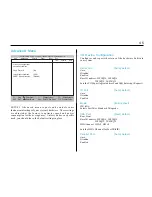
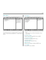
Page 41: ...ettings in a battery sustained CMOS chip If the battery is low you may repeatedly get a SETUP error during bootup If you see error messages when you turn on your machine call your dealer immediately Do not open the system yourself Chapter 3 Hardware Setup The Main menu Figure 3 1 SETUP s Main menu Note You can see and adjust your system s basic settings with the Main menu When you start the SETUP ...

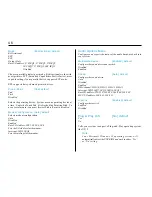
Page 42: ...u boot from a floppy or the CD module and 1 through 39 industry standard drive types When set to User you can manually adjust your drive s parameters System Date dd mm yy Sets your system s calendar Primary Master C XXXX MB Reports the drive letter of your system s main drive and its capacity in megabytes The submenu lets you adjust drive parameters Note None can be selected by pressing the spaceb...

Page 43: ... modular external hard drive Its settings are the same as IDE Adapter 0 Master see previous Memory Cache Enabled default Lets your system use the 512K of synchronous pipelined burst cache The extremely quick access time 10 nanoseconds of this memory greatly boosts system performance Boot Options Summary Screen Shows system parameters on boot Quick Boot Mode Allows the system to skip certain tests ...

Page 44: ...Fast IR FIR Parallel Port Auto default Auto Disabled Enabled Advanced Menu SETUP s Advanced menu reports and controls some fundamental settings of your system s hardware These settings are adjusted at the factory to optimize speed and power consumption for the average user Unless you have a specific need you should leave the default settings in place Phoenix BIOS Setup Copyright 1985 95 Phoenix Te...

Page 45: ...t the PNP BIOS and work in either Yes or No setting Mode Bi Directional default Bi Directional EPP ECP Output Only Base I O address 378 IRQ5 378 IRQ7 278IRQ7 3BC IRQ7 278 IRQ5 3BC IRQ5 Disabled Chooses parallel printer port mode Bi directional works with most printers ECP Extended Capabilities Port is fastest most capable setting if your parallel device supports ECP mode EPP supports daisy chained...

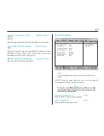
Page 46: ...sswords on bootup Stop If you lose your BIOS password you ll have to ship the computer back to the factory to have the password removed at your expense Supervisor Password is Clear Reports status of supervisor password User Password is Clear Reports status of user password Phoenix BIOS Setup Copyright 1985 95 Phoenix Technologies Ltd F1 Help Select Item Change Values F9 Setup Defaults ESC Exit Sel...

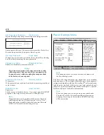
Page 47: ...onfirm New Password Phoenix BIOS Setup Copyright 1985 95 Phoenix Technologies Ltd F1 Help Select Item Change Values F9 Setup Defaults ESC Exit Select Menu Enter Select Sub Menu F10 Previous Value Main Advanced Security Power Boot Exit Item Specific Help Select Power Management Mode Choosing modes changes system power management settings Maximum Power Savings conserves the greatest amount of system...

Page 48: ...cularly well when using your computer on an airplane or a train where you may want your machine ready to resume work quickly between breaks Suspend Timeout 10 min default 5 10 15 20 30 40 or 60 minutes Off Howlongyoursystem waitsbefore enteringthemoreaggressive Suspend mode These choices become available after you select Customize as your PowerSavings setting Suspend is the third level of power co...

Page 49: ... default 10 15 or 30 seconds or 2 4 6 8 10 or 15 minutes Disabled Time that all user input devices are inactive before video turns off Resume on Modem Ring On default Off Revives the system when the modem detects an incoming call This lets your system stand ready to receive modem or fax messages even if an AC power outlet is unavailable The option is for the internal modem only It will have NO eff...

Page 50: ...Phoenix Technologies Ltd F1 Help Select Item Change Values F9 Setup Defaults ESC Exit Select Menu Enter Select Sub Menu F10 Previous Value Main Advanced Security Power Boot Exit Item Specific Help To Select the boot device use the up and down arrows then press to move the device up the list or to move it down the list Press Esc to exit this menu 1 Diskette Drive 2 ATAPI CD ROM Drive 3 Hard Drive P...

Page 51: ...en you upgrade with optional RAM modules Table 4 1 RAM configurations Note Micron Electronics may not carry all of the below specified memory configurations RAM onboard Modules added Total 32MB onboard one 32MB module 64MB 32MB onboard two 32MB modules 96MB 64MB onboard one 32MB module 96MB 64MB onboard two 32MB modules 128MB 64MB onboard one 64MB modules 128MB 64MB onboard two 64MB modules 192MB ...

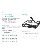
Page 52: ...for upgrades Memory Module Removing the internal hard drive The internal EIDE hard drive is located on the right side of the computer behind the right bay The drive is secured by a single retaining screw on the underside of the machine Tool A medium Phillips screwdriver To remove the internal hard drive 1 Power down the machine completely 2 Remove the retaining screw 3 Carefully pull out the drive...

Page 53: ...Figure 4 4 Inserting a floppy drive module into Left Bay Removing a hard drive or floppy drive module Figure 4 5 Removing a floppy drive module To remove the floppy disk drive from the left bay 1 Turn off the system then unplug it from outside power 2 Turn the computer over then place your fingers in the groove on the disk drive Slide back the release latch and simultaneously pull firmly on the mo...

Page 54: ...ain the proper drivers are included on a CD with your system Figure 4 6 Removable CD ROM drive Manual Release Pin Hole Drive Access Lamp Disk Eject Button The CD ROM player goes in the right bay To install the unit first power down the system completely open the sliding door then slide the drive into the bay until you hear the latches click Warning Always turn off your computer before you remove o...

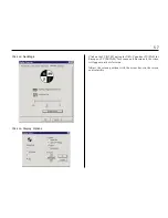
Page 55: ...ut that will be used When using the Windows 95 operating system you will need to have the system running and do the following steps Click on MY COMPUTER Click on CONTROL PANEL Click on DISPLAY Click on SETTINGS Verify that the resolution is set for 640x480 or 800x600 under the desktopareaoptionas well asthescreen area After changing one or both options select apply then click on the OK button Figu...

Page 56: ...isplay Options Click on the TV NTSC option for USA Canada or TV PAL for Europe or TV SECAM for France and Russia and the video will appear on the television Adjust the screen position with the arrow keys in the screen control utility ...

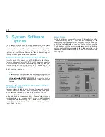
Page 57: ...oses only should you at some time need to reload your system software Windows 95 and Windows NT 4 0 Workstation Save to Disk Partition On your primary hard disk drive Micron Electronics has placed a special non DOS partition that allows your system to suspend to disk instead of memory When you use the save to disk feature the TransPort saves your current viewing environment to the hard disk and th...

Page 58: ...y once you click on your power profile Please see Chapter 3 of this guide for further information on system Power Management settings Under Windows NT 4 0 Power Panel adds Advanced Power Management APM functionalitythatwouldotherwisenotbeavailable on a Windows NT system Power Panel for Windows NT 4 0 operates in much the same way as the Windows 95 version does as described above Please note howeve...

Page 59: ...om Softex Inc allows you to hot dock and undock your TransPort XKE on your optional Micron Dock with the same ease as in Windows 95 Please see Chapter 1 in this guide for further information on Windows 95 hot docking and undocking ...

Page 60: ...hield your modem from damage caused by accidentally plugging it into a digital phone line In addition to standard fax modem functions the modem supports the following features when used with a software application that supports voice functions Answering machine listen to your phone messages from your computer Voice mail save the messages you need in voice mailboxes Speaker phone have phone convers...

Page 61: ...t to the maximum i e 115200 Digital Phone Lines Digital phone lines found in some office buildings and hotels may generate high voltages that can damage a modem s internal circuitry Toprotectthemodemfromsuchdamage thereisbuilt in digital line protection Using Calling Cards The modem detects the bong sound you hear when you place a call using a calling card To enable your modem to automatically ent...

Page 62: ... DistinctiveRing is compatible only with U S A standards Using the Speakerphone You can access the speakerphone capabilities through the communications software on your computer CAUTION Make any modifications to speakerphone controls including volume and audio compression through the communications software Adjusting these controls through the control panel may cause the speakerphone to malfunctio...

Page 63: ...ttached to the computer it remains off until you place your next call This helps conserve the phone s battery power If both the RJ 11 and cellular phone cables are connected the cellular phone is used to place the call Optimizing Cellular Data Connections Many factors can affect the transmission quality of cellular phones including interference from buildings walls electronic equipment and street ...

Page 64: ...the COM port assigned to the modem Confirm the modem is in auto answer mode Restart the communications software package Type ATS0 n where n equals the number of rings before call pickup Check the phone line make sure it is properly connected to the modem s cable Verify that you are using an analog phone line The modem does not work with digital or PBX phone lines Restore factory settings by typing...

Page 65: ...op of DTR using AT D2 Make sure that the computer s flow control setting is the same as the modem s setting e g XON XOFF Contact the technical support group for information on how to upgrade modem software Disconnect the RJ 11 cable from the wall outlet Find an analog phone line to plug the modem into Determine which file transfer protocol you are using Refer to the communications software manual ...

Page 66: ...commandstring Nottobepreceded with AT or followed by pressing the Return key Answer Command Instructs the modem to go off hook and answer an incoming call Pressing any key aborts the operation Attention Command Required prefix for all commands unless otherwise noted Use alone to test for OK result code Communication standard setting determines CCITT vs Bell standard Selects CCITT V 22 mode when th...

Page 67: ...o on line data mode Select Pulse Dialing Configures the modem to use pulse dialing Dialed digits are pulse dialed until a T command or dial modifier is received e g ATDT Tone dial is the default setting ResultCodeDisplayOption Controlswhethertheresultcodesaredisplayed to the DTE Result codes enabled Result codes disabled EnableToneDialing InstructsthemodemtouseDTMFtoneswhiledialing Dialed digits a...

Page 68: ...rol Selects the method the modem provides to the DTE to prevent the modem s buffer from overflowing Disable flow control Enable bi directional hardware flow control RTS CTS Enable bi directional XON XOFF flow control Asynchronous Synchronous Mode Selection Selects synchronous or asynchronous operation and synchronous dial methods This command is only valid if the modem supports synchronous connect...

Page 69: ... mode Error control is disabled Flow control is not allowed Slaved DTE DCE is enabled MNP or disconnect mode LAPM MNP or normal mode LAPM mode Same as N3 Same as N3 Qn Q0 Q1 Q3 TN T0 TN Vn V0 V1 Xn X0 Flow Control Settings Selects the method the modem uses to prevent overflowing the buffer with data Disable flow control Enable bi directional XON XOFF flow control Enable bi directional CTS RTS flow...

Page 70: ...NECT 115200 Connection rate at 115200 BPS 88 DELAYED Onblacklist willattempttoplacecallagain 89 BLACKLISTED Too many attempts to same number call will not go through 90 BLACKLIST FULL Nomorespacetostoreblacklistednumbers S Registers S0 through S19 S Reg RO RW Function Range Default S0 RW Ring to answer 0 255 0 auto answer off S1 RO Ringcount 0 255 0 S2 RW Escape sequence character 0 255 43 S3 RW E...

Page 71: ...mpt a 48000 BPS connection 11 Attempt a 50000 BPS connection 12 Attempt a 52000 BPS connection 13 Attempt a 54000 BPS connection 14 Attempt a 56000 BPS connection S42 Auto Rate for 56K 0 Range 1 Enabled S Registers S72 S89 S108 S Reg Function Range S72 Reserved functionality taken over by S16 S89 Automatic Sleep Timer Specifies how long Default 10 min 0 max 65 in seconds the controller waits befor...

Page 72: ...l fluid gets into your eyes or on your hands immediately wash the affected areas with water for at least 15 minutes then get medical care if any symptoms of irritation are present after washing Disk Drives Your system comes with a low power consumption removable hard disk drive and a 3 5 inch floppy disk drive Caution Protect the computer from being jarred and from strong vibrations Protect the co...

Page 73: ...lity More on floppy disk CAUTION Use only clean dry and undamaged floppy disks Protect both floppy disk and the insertion slot of the floppy drive from grit dust or dirt Keep floppy disk away from magnetic sources and protect floppy disk from excessive cold or heat below 5 C 41 F and above 60 C 140 F Be careful to format the disk according to the disk type Touch Pad Warning Do not strike or scratc...

Page 74: ...onsequent fire Avoid use of AC adapter on electrically heated carpet or near heating appliances Disconnect from AC mains supply when not in use Don t hit drop or subject the AC adapter to strong vibrations Don t leave the AC adapter in direct sunlight Don t store the AC adapter where it is uncomfortably hot Avoid using the adapter in a humid or dusty environment Don t leave the AC power cord plugg...

Page 75: ...en inserting the battery pack in a computer be sure to install it in the manner specified Forcibly connecting the battery when it will not connect smoothly could cause the battery pack to overheat catch fire or otherwise be damaged Do not connect the battery to a power outlet or to a cigarette lighter type outlet in a car This battery pack is designed for use with the TransPort XKE system only Do ...

Page 76: ...rared 2 one front one rear Transfer rate 2 400 to 115 000bps IRDA mode 4 Mbits sec FIR mode Parallel EPP ECP with Centronics standard 25 pin female connector Serial RS 232C 9 pin 16550AF compatible Video SVGA compatible 15 pin female connector TV out NTSC video out interlaced 525 lines horizontal 30fps S Video output connector 5 pin DIN Mouse PS 2 style 6 pin mini DIN Keyboard PS 2 style 6 pin min...

Page 77: ... female connector Serial 9 pin male connector Ext Monitor SVGA compatible 15 pin female connector Power supply AC input 100 240V AC 1 3 0 7A 50 60Hz DC output 19V Operating Conditions Ambient temperature Operating 50 to 95 F 10 to35 C Recommended 50 to 80 F 10 to 27 C Off state 14 to 112 F 10 to 50 C Humidity Operating 40 to 80 no condensation Off state 40 to 80 no condensation TV out NTSC video o...

Page 78: ...MNP2 4 Fax Modem Specifications Compatibility Interface EIA 578 Asynchronous Facsimile Modem Control Standard Service Class 1 and Class 2 Standards ITU V 17 14 400 12 000 9600 7200 TCM ITUV 29 9600 QAM 7200 QAM ITU V 27ter 4800 DPSK 2400 DPSK ITU V 21 Channel 2 300 FSK Voice Modem Specifications Supports independent speaker mic positioning Full duplex speakerphone Echo cancellation gain maximum Su...

Page 79: ...e 2 ONOW EX would represent any five character filename ending in ONOW with EX as the first two characters of its extension Quick Reference Sheet The following commands and buttons are useful for this personal computer CTRL ALT DEL Warm Reboot POWER button Cold Reboot F2 during bootup Run BIOS SETUP CTRL BREAK or CTRL C Pause or Break a DOS program or batch file DOS Commands COPY filename drive pa...

Page 80: ...e battery pack unplug the AC adapter from the wall outlet and contact your dealer Don tattempttodismantleormodifythiscomputer There are no user serviceable parts inside Don t use the computer in a bathtub or shower When connecting peripheral equipment read the operating manual for each device turn off the system then make the appropriate connections Don t place your computer on an unsteady surface...

Page 81: ...arranty One Year Limited Warranty and Ninety Day Replacement Parts Limited Warranty cover only defects arising under normal use and do not include malfunctions or failures resulting from misuse abuse neglect alteration problems with electrical power usage not in accordance with product instructions acts of nature unusual temperatures or humidity improper installation or damage to the LCD display s...

Page 82: ...TIONS DO NOT ALLOW THE EXCLUSION OR LIMITATION OF INCIDENTAL OR CONSEQUENTIAL DAMAGES SO THE ABOVE EXCLUSION OR LIMITATION MAY NOT APPLY TO YOU NO VARIATION OR EXCEPTIONS IN THE TERMS STATED HEREIN CAN BE MADE WITHOUT WRITTEN AUTHORIZATION BY THE PRESIDENT OF MICRON A FULL REFUND AS USED HEREIN SHALL INCLUDE THE PURCHASE PRICE PAID BY THE CUSTOMER BUT SHALL NOT INCLUDE SHIPPING COSTS INSURANCE AND...

Page 83: ...erein you may return the product s to Micron for a full refund of the purchase price paid less any restocking charge for opened software This policy does not include payment by Micron for original or return shipping handling and insurance charges and if applicable import and export duties and all other fees and charges imposed by government or quasi governmental agencies or officials all of which ...

Page 84: ...pressly approved by the party responsible for compliance could void the user s right to operate this equipment Peripherals used in conjunction with this equipment must be connected via shielded interface cables Use of unshielded interface cables may result in interference to radio and TV reception and may void the user s right to operate this equipment Shielded interface cables must be used in ord...

Page 85: ...information into your messages you should 1 Refer to the Page Header instructions provided in the manual of the FAX software you are using 2 Enter information into the program including The date and time the message is sent Your identification information Special Requirements for Canada CertainrequirementsexistfordatacommunicationproductsmanufacturedforuseinCanada Principle among these requirement...

Page 86: ... and produces the least fatigue The backrest should adjust to fit the small of your back Use an adjustable keyboard support You want to keep your wrists straight your hands lower than your forearms and your forearms parallel to the floor Use a light touch on the keyboard Alternate mouse and keyboard use and keep the mouse within easy reach Place the notebook 18 30 inches from your eyes arm s lengt...

Page 87: ... The programs you use are temporarily stored in RAM All data stored in RAM is erased when you turn off the power Read To copy data from one area to another For example when you open a text file stored on disk the computer reads the data from the disk and displays it on the screen Reset To reload a computer s operating system so you can retry a task or begin using a different operating system Reset...

Page 88: ...3 suspend resume 26 Cellular phone connecting 25 D Disk drives 23 precautions 72 DOS commands 79 DOS file extensions 79 E Ergonomics 86 Exit menu 50 Expansion bays 9 F FCC Notices 84 Floppy Disk Drive care 73 G Getting started 5 Glossary 87 H Hard Disk Drive removing 52 Headphones 73 Hot keys 16 Howling 10 Humidity 7 I Infrared IR port 9 24 Internal pointing devices 14 K Keyboard 15 L LCD Indicato...

Page 89: ...63 connecting 25 63 default initialization string 61 digital phone lines 61 features 60 specifications 77 troubleshooting 64 upgrading 60 N Note Dock 59 NTSC setup 55 Numeric keypad 15 P Passwords 46 PC card slots PCMCIA 22 Pointing stick 14 Power Panel Phoenix 58 Power Savings menu 47 R RF suppressor 6 Right expansion bay 21 S Safety 80 Security menu 46 Setup running 41 System features 8 System S...

Page 90: ...9 1 MAS 001412 02 MAS10091 MAN 01 10 97 ...

Reviews: