Technical and Functional Details
Peripheral Controls
GDUTUG500/01
CE-500 MDT Hardware Guide
36 / 97
A
A
n
n
a
a
l
l
o
o
g
g
I
I
n
n
p
p
u
u
t
t
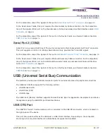
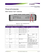
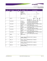
The platform provides an analog input signal to monitor the voltage range of compatible vehicle sensors,
such as an analog fuel gauge. This signal is connected to the Main Terminal “Con1” connector, which is
located on the bottom panel of the device.
The supported voltage range is from 0V to 30V.
For the disposition map of this signal on
Main Terminal “Con1” Connector
, see page
In the Fixed-mount mode, this port requires the Enhanced Accessory Cable connection. For the
disposition map of the signals of this port on the Accessory Cable Enhanced Interface cable, see
For the position of this signal on the Device Cradle, see
Connector, on page
1
1
-
-
W
W
i
i
r
r
e
e
I
I
n
n
t
t
e
e
r
r
f
f
a
a
c
c
e
e
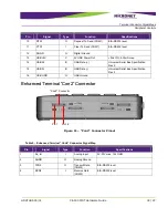
The platform provides the 1-Wire Interface Port connected to the Main Terminal “Con1” connector,
which is located on the bottom panel of the device.
This port provides control, signaling, and power over a single-wire connection. Developers can connect
an optional touch probe accessory and use Dallas ID Memory
DS1990A
64 bit ID Buttons for
identification and authorization control. See
ic.com/products/ibutton/ibuttons/memoryoverview.cfm
For the disposition map of this signal on
Enhanced Terminal “Con2” Connector
, see page
In Fixed-mount mode, this port requires the Enhanced Accessory Cable connection. For the disposition
map of the signals of this port on the Accessory Cables Enhanced Interface cable, see
For the position of this signal on the Device Cradle, see


