Platform Accessories
Accessory Cables
GDUTUG500/01
CE-500 MDT Hardware Guide
66 / 97
Pin
Signal
Function
Wire Size (AWG)
Required
3
Dig_In2
Digital Input 2
28
4
N/C
Not connected
5
RXD2
Receive Data (COM2)
28
6
DGND
Digital Ground
28
7
An_In1
Analog Input
28
8
AGND
Analog Ground
28
L
L
A
A
N
N
C
C
o
o
n
n
n
n
e
e
c
c
t
t
o
o
r
r
NOTE:
The Ethernet LAN interface is an optional platform feature. The interface signals described
below present on this connector only if the device supports these signals. Otherwise, the
connector pins are not connected and must not be used.
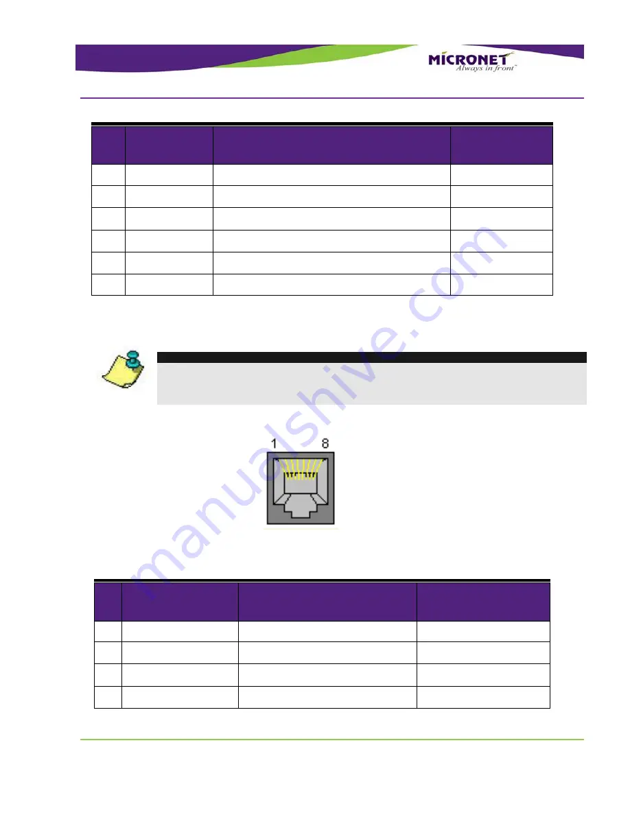
Connector type –RJ45
Figure 33
– Enhanced Interface Cable LAN Connector Pinout
Table 14
– Enhanced Interface Cable LAN Connector Signal Map
Pin
Signal
Function
Wire Size (AWG)
Required
1
Ethernet LAN Transmit Data +
24
2
LAN_TX-
Ethernet LAN Transmit Data -
24
3
Ethernet LAN Receive Data +
24
4
N/C
Not connected


