Technical and Functional Details
Peripheral Controls
GDUTUG500/01
CE-500 MDT Hardware Guide
34 / 97
For the disposition map of the signals of this port on the Device Cradle, see Device Cradle connectors
, on page
E
E
t
t
h
h
e
e
r
r
n
n
e
e
t
t
C
C
o
o
m
m
m
m
u
u
n
n
i
i
c
c
a
a
t
t
i
i
o
o
n
n
(
(
O
O
p
p
t
t
i
i
o
o
n
n
)
)
The platform optionally provides the Ethernet LAN communication port, connected to the Enhanced
terminal “Con2” connector, which is located on the bottom panel of the device. The Ethernet LAN
communication is a factory set option.
NOTE:
Other optional modular-platform features can be separately ordered and installed by the
customer. However, this option can only be included in the device by Micronet during
device manufacturing and cannot be added afterward. You must specify the Ethernet
option requirement with the device order.
This port is fully compliant with IEEE 802.3 / 802.3u standards and supports 10BASE-T and 100BASE-TX
functionalities.
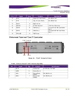
For the disposition map of the signals of this port on
Enhanced Terminal “Con2” Connector
, see page
In the Fixed-mount mode, this port requires Enhanced Accessory Cable connection. For the disposition
map of the signals of this port on the Accessory Enhanced interface Cable, see
on page
For the disposition map of the signals of this port on the Device Cradle, see Device Cradle
, on page
P
P
e
e
r
r
i
i
p
p
h
h
e
e
r
r
a
a
l
l
C
C
o
o
n
n
t
t
r
r
o
o
l
l
s
s
D
D
i
i
g
g
i
i
t
t
a
a
l
l
I
I
/
/
O
O
D
D
i
i
g
g
i
i
t
t
a
a
l
l
I
I
n
n
p
p
u
u
t
t
s
s
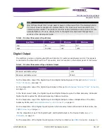
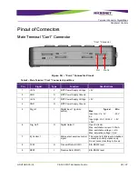
The platform provides two digital inputs at the automotive voltage level for monitoring and controlling
external peripherals or sensor signals. These signals are connected to the Main Terminal “Con1” and
“Con2” connectors, which are located on the bottom panel of the device.


