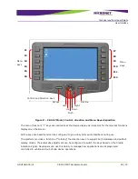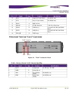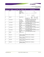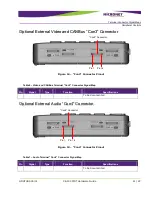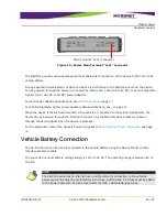
Terminal Connector Signal Maps
Peripheral Controls
GDUTUG500/01
CE-500 MDT Hardware Guide
37 / 97
3
3
T
T
e
e
r
r
m
m
i
i
n
n
a
a
l
l
C
C
o
o
n
n
n
n
e
e
c
c
t
t
o
o
r
r
S
S
i
i
g
g
n
n
a
a
l
l
M
M
a
a
p
p
s
s
O
O
v
v
e
e
r
r
v
v
i
i
e
e
w
w
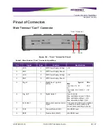
This chapter describes the Basic (“Con1” and “Con2”) and Full (“Con3” and “Con4”) connectors
configuration. The power, communication and I/O signals in the Basic configuration, and the Video,
CANBus and Audio signals in the Full configuration.
All pins are ESD protected (against electrostatic discharge).
All the “shield” pins of the connectors are attached to the Ground signal.
The following abbreviations are used in this chapter:
I - Input signal
O - Output signal
B - Bus signal
V - Voltage signal
G – Ground
All the four connectors' type is Molex
™ I/O Interconnect System part number - 0448281162.


