background image

6.2

Setup and Calibration Operation

To enter Setup

Warning:

It is not possible to enter setup mode while the Race Timer

(TMR) or Wind Shift (WND) page is currently visible. Scroll to a different
page in order to enter setup
Press and hold 

, the first chapter title page is displayed

To change the active chapter

Press 

repeatedly until the desired chapter title page is displayed.

At the end of the chapter cycle, the display returns to the first chapter
title page.
If you are currently on a chapter parameter page, you must return to the
chapter title page before you can move to a new chapter. 

To access the setup pages

Use 

to scroll through the pages. 

returns to the previous page.

6.3

Editing Setup Data

Parameter values may be one of four types:

A user editable numeric value

(for example, the magnetic variation

may have the value 03 degrees)

To edit a numeric parameter value:
Press 

. The value data will begin to flash.

Use 

and 

to adjust the value.

Press 

again to set the new value.

A resetable numeric memory value

(for example the average speed

memory can be reset to the current speed)

To reset a memory value:
Press 

. The parameter is reset.

A list of options

(for example, the heading response parameter may

have the values SLO , mED or FASt).

To select a parameter option from a list:
Press 

.The parameter option will begin to flash.

Use 

and 

to select the option required.

Press 

again to set the new option.

A toggle between two alternative options

(for example the keylock

parameter can be either ON or OFF)

To toggle between alternate parameter settings:
Press 

. The setting will toggle between the options.

Race Master System

20

Summary of Contents for T075-916

Page 1: ...Race Master System User Guide...

Page 2: ...ns the skippers responsibility to maintain a permanent watch and be aware of developing situations Any attempt to take a Micronet product apart will invalidate the warranty The battery may only be rep...

Page 3: ...Micronet Functions 14 5 1 Chapter and Page Operation 14 5 2 Display Modes 16 5 3 Depth Pop up and Depth Shallow Alarm 16 5 4 Speed Trim 16 5 5 Bar Graph Functionality 17 5 6 Page Hiding 18 5 7 Operat...

Page 4: ...cing compass with functions for capturing the mean wind direction wind shifts and the starting line bias Networked Speed and Depth Using the networked Hull Transmitter with the depth and speed transdu...

Page 5: ...agement By reducing the amount of power being used by the electronics and maximizing the potential of the sun to provide power the Micronet Race Master System is capable of virtually perpetual operati...

Page 6: ...SAVE alarm will sound before the system switches off Pressing any button within 10 seconds of the alarm sounding will allow the system to remain switched on 2 5 Backlighting At any stage of the displ...

Page 7: ...er up The display will issue a single beep as it is switched on Button Press A single beep is issued each time a button is pressed A second beep is issued when a button has been held down for two seco...

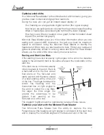
Page 8: ...to gusts but find wind shifts more difficult to detect However the wind does tend to shift in regular patterns oscillating from one side of the Mean Wind Direction MWD to the other Every shift in the...

Page 9: ...d Micronet Race Master shows you the wind shifts more clearly than ever before Racing and Start Line Bias If the starting line is laid at exactly right angles to the wind the distance sailed to the wi...

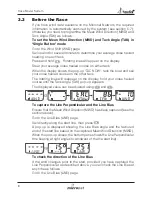
Page 10: ...ther tack The rotating lines will reappear on the display hold your close hauled course until the Tack Angle TAK pop up appears The displayed value can be adjusted using and To capture the Line Perpen...

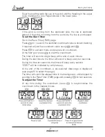
Page 11: ...xit edit mode and prepare for countdown At the first gun press to start the countdown The timer will sound a single beep at the end of each minute During the last minute the timer will sound a beep ev...

Page 12: ...e you should tack on digital or bar graph indications Permanent wind shifts These can be recognised as a constant header on one tack and a constant lift on the other tack In this situation you can adj...

Page 13: ...o at the bottom of the display For example at 45 degrees the bar graph is almost full length and the boat is sailing at 45 degrees from the mean downwind direction When the Wind Shift WND page is sele...

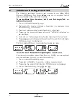
Page 14: ...ed heading on either tack 4 Press the display will beep twice and TAC NOW will show for two seconds 5 Tack and sail your average close hauled heading on the new tack 6 Press again the display will bee...

Page 15: ...quired value using and To correct the Mean Wind Direction MWD by going head to wind For Wind Shift to work correctly you must ensure that the tack angle is captured using one of the methods described...

Page 16: ...e full set of data displays that are available For a detailed description of individual data items supported on the Micronet network see the Micronet Data user guide on your product CD or on the Tackt...

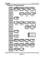
Page 17: ...Micronet Functions 15 Chapter and Page Diagram...

Page 18: ...and shallow water alarm can be configured in setup Depth Pop up When the depth is less than a pre set value the Depth page automatically replaces the data item displayed in the lower pane The Depth pa...

Page 19: ...sing a fixed scale of 25 degrees about a central zero Each segment of the graph corresponds to 2 5 degrees of shift Downwind the graph indicates the angle sailed relative to the Mean Wind Direction MW...

Page 20: ...ata on the network When Wind data is available on the network operation of the Race Master wind and line bias functions is simplified Mean Wind Direction MWD is automatically calculated as an average...

Page 21: ...ised into Chapters each comprising a number of Pages Setup pages use both the top and bottom panes of the display The diagram below shows the layout of the available chapters and pages In Micronet mod...

Page 22: ...ter values may be one of four types A user editable numeric value for example the magnetic variation may have the value 03 degrees To edit a numeric parameter value Press The value data will begin to...

Page 23: ...the units in which ALL Distance related information is displayed The options available are NM Nautical Miles KM Kilometres or SM Statute Miles Wind Speed Units The units in which ALL wind speed relate...

Page 24: ...ecimal places to which the boat speed information is displayed The options are 0 1 or 0 01 Speed Trim Range Sets the full scale display value of the speed trim bar graph The value can be set from 25 t...

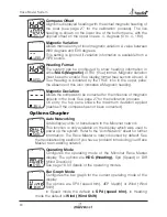
Page 25: ...ngle Offset Aligns the displayed apparent wind angle with the actual wind direction See page 30 for the calibration process The live wind angle is shown in the top pane with the tack shown as PRT or S...

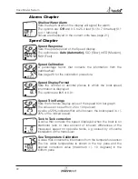
Page 26: ...e influence of magnetic objects in the boat See page 27 for the calibration process On entry the top pane shows the maximum deviation applied dashes if the compass has not been corrected Options Chapt...

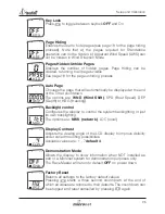
Page 27: ...Wind Shift SPD Boat Speed DEP Depth or HDG Heading Backlight control Configures the display to control the system backlighting or just its own backlighting The options are NWK network LOC local Displ...

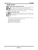
Page 28: ...shown in the top pane otherwise signal strength is shown in the top pane Hull Transmitter status Shows the signal strength software version battery level and charge rate of the Hull Transmitter to ass...

Page 29: ...essel slowly keeping the speed below 4 knots and taking approximately 2 minutes to complete 360 degrees Keep turning the vessel until the display changes to show a value usually about 1 25 turns Note...

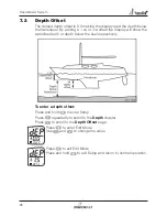
Page 30: ...e waterline depth or depth below the keel respectively To enter a depth offset Press and hold to enter Setup Press repeatedly to scroll to the Depth chapter Press to scroll to the Depth Offset page Pr...

Page 31: ...the factors determined by the two runs To enter a Speed Calibration Factor With the vessel under power steer a straight course and allow the boat speed reading to settle to a constant value Check the...

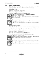
Page 32: ...Press and hold to exit Setup and return to normal operation Wind Speed Correction Note The Wind Speed reading is factory calibrated to display correctly and should not be altered unless external fact...

Page 33: ...s far as possible from magnetic objects that might interfere with the compass sensor Attach the Cradle to a suitable bracket or bulkhead using the bolts or screws supplied Take care to ensure the plan...

Page 34: ...y symbol flashes and the unit switches off The Race Master battery level is low Leave the Race Master in bright sunlight for 12 hours minimum to recharge the internal battery Low Battery Alarm sounds...

Page 35: ...zero then there is a problem with your Wind Transmitter No NMEA data showing on external displays Enter Setup and Calibration Mode scroll to the Health Chapter and check the signal level and battery s...

Page 36: ...rightest backlighting 20 nights at economy backlighting without charge Units of display Boat Speed knots kilometres per hour statute miles per hour Distance nautical miles statute miles kilometres Dep...

Page 37: ...ducts that have been incorrectly installed or have serial numbers removed will not be covered No compensation is payable for consequential damage caused directly or indirectly by any malfunction of Ta...

Page 38: ...s only Labour handling costs and return shipping will be invoiced to the sender Disclaimer Tacktick products should only be considered an aid to navigation and common sense must be applied at all time...

Reviews:

Related manuals for T075-916