7
www.micronfilter.it
ENGLI
SH
4.0 INSTALLATION
THE CLEANER MUST BE INSTALLED BY SPECIALISED PERSONNEL
The place where the cleaner is to be installed must be spacious enough to make it possible to
access the machine comfortably and safely, for all routine or extraordinary maintenance
operations.
4.1 POSITIONING THE CLEANER
Make sure the place where the cleaner is to be installed is perfectly flat. Lift the cleaner using
the hooks and place it in its seat, in the tank.
4.2 CONNECTION TO THE WATER MAINS
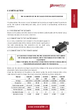
Use a hose connection (not included in the standard supply) to
connect a flexible tube to the entrance of the cleaner (see figure on
the side). Alternatively, this connection can be made using
hydraulic components (tubes, elbows etc), suitably sized.
4.3 CONNECTION TO THE POWER MAINS
ALL ELECTRIC CONNECTIONS FOR THE CLEANER MUST ONLY BE CARRIED
OUT BY SKILLED ELECTRICIANS, WITH THE POWER CUT OFF FROM THE
EQUIPMENT.
PRIOR TO MAKING THE ELECTRIC CONNECTIONS FOR THE CLEANER, CHECK
THE WIRING DIAGRAM ATTACHED TO THIS MANUAL.
Make sure the connection voltage is equal to the voltage of the power grid (check the plate
attached to the terminal of the motor reducer).
Check the information on the plate on the cleaner (verify the electric characteristics in the
table below) in order to choose the proper connection materials (sections, cables etc).
Cleaner
Kalamit
75
Kalamit
150
Kalamit
250
Kalamit
350
Kalamit
500
Voltage
230/400
V
230/400V
230/400V
230/400V
230/400V
Frequency
50 HZ
50 HZ
50 HZ
50 HZ
50 HZ
Total rated power
0.12 kW
0.12kW
0.12kW
0.12kW
0.12kW
Current at full power
0.62A
0.62A
0.62A
0.62A
0.62A
Motor reducer
Double
Double
Double
Double
Double
Number of poles
6
6
6
6
6
Reduction ratio
1/600
1/600
1/600
1/600
1/600

