D5CUB System Board Manual
4
List of Figures
Figure 1.1: Power-Up Screen
Figure 2.1: D5CUB System Board
Figure 3.1: Installing a 72-Pin SIMM
Figure 3.2: Installing a CPU
28
Figure 3.3: Installing an ISA Peripheral Card
Figure 3.4: Connecting the Sound Interface Card
Figure 4.1: Power-Up Screen
Figure 4.2: Main CMOS Setup Screen
Figure 4.3: Standard CMOS Setup Screen
Figure 4.4: BIOS Features Setup Screen
Figure 4.5: Chipset Features Setup Screen
Figure 4.6: Power Management Screen
Figure 4.7: PnP/PCI Configuration Screen
Figure 4.8: Integrated Peripherals Screen
Figure 4.9: IDE HDD Auto Detection Screen
Figure 4.10: HDD Low Level Format Screen
List of Tables
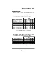
Table 2.1: System Speed Selection (Intel)
Table 2.2: System Speed Selection (Cyrix)
Table 2.3: Power Supply Voltage Selection
Table 2.4: Pentium CPU Type Selection
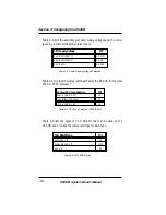
Table 2.5: TAG SRAM Type Selection
Table 2.6: Multi I/O Chipset Selection
Table 2.7: Sound Interface Selection
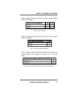
Table 2.8: CPU Internal Cache Selection
Table 2.9: Clear CMOS Memory Selection
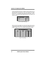
Table 2.10: Clock Ratio Selection
Table 2.11: Jumper Settings & Functions
Table 2.12: Connector Settings and Functions
Table 3.1: Memory Configurations


