background image

Micronics M4Pi System Board Manual

4-12

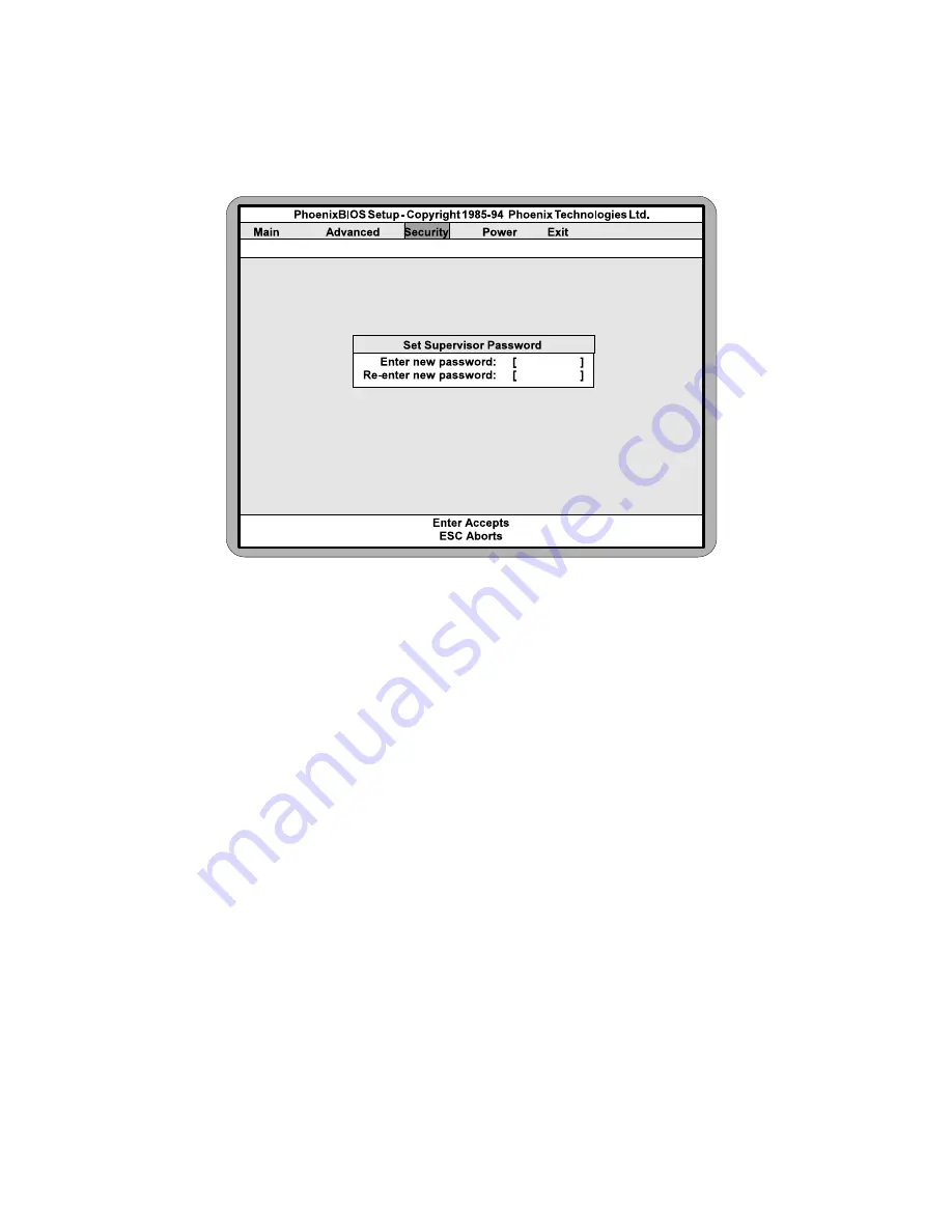
Figure 4-8  Supervisor Password Submenu

Type the password and press the <Enter> key.  Retype the password and press
the <Enter> key again.  Write down the password somewhere safe so it will
not be forgotten.  The password may be disabled by setting the new password
to nothing (pressing the <Enter> key without first typing a password).

Warning:
If you forget the Supervisor Password, it cannot be disabled without dis-
charging the CMOS.

Set User Password

Follow the same procedure used to set the Supervisor Password.

Note:
When a password has been entered, it is saved immediately.  All other changes
may still be discarded (see Exit Screen).

Password on Boot

When enabled, the system will require a password to be entered upon boot.
Either the Supervisor or User Password may be entered.

Diskette Access

Summary of Contents for M4Pi Series

Page 1: ...M4Pi PCI ISA System Board Manual ...

Page 2: ...M4Pi PCI ISA System Board Manual Document Number 06 00209 03 Rev 3A November 1995 221 Warren Ave Fremont CA 94539 7085 ...

Page 3: ...may be photocopied repro duced translated or reduced to any medium or machine form without prior written consent from Micronics COPYRIGHT C 1995 Micronics Computers Inc Portions of the Manual Portions of this manual were copied with permission from Phoenix Tech nologies Ltd Trademarks IBM is a registered trademark of International Business Machines Microsoft Microsoft Word Windows are registered t...

Page 4: ...iskettes 2 Ground yourself to prevent damaging static discharge then remove the M4Pi from its packaging 3 Configure and verify the system board s jumper settings See Jumper Settings in Chapter 2 4 Install the CPU and the system memory Chapter 3 5 Install the system board into the chassis and make all necessary case connections 6 Install any peripherals Chapter 3 7 Turn the computer on and press th...

Page 5: ...selected and the BIOS will automatically configure the drive for you See Chapter 4 9 After you have configured the Main Setup menu make any desired setting configurations in the Advanced and Security menu When finished go to the exit screen select Save Changes and Exit and you are finished with the BIOS configuration Chapter 4 The system is ready to be loaded with software and used iv ...

Page 6: ... Required 3 2 Equipment Required 3 2 SystemMemory 3 3 SIMMs Supported 3 3 Memory Configurations 3 3 Installing the SIMMs 3 4 Removing SIMMs 3 4 InstallingaCPU 3 5 Installing256KofCacheMemory 3 6 InstallingaPCIPeripheralCard 3 7 InstallinganISAPeripheralCard 3 8 The BIOS Setup Utility 4 1 Configuration 4 1 InitialBootUp 4 1 Setup 4 2 RunningtheSetupProcedure 4 3 SettingtheMainScreen 4 3 System Time...

Page 7: ...pervisor Password is 4 11 User Password is 4 11 Set Supervisor Password 4 11 Set User Password 4 12 Password on Boot 4 12 Diskette Access 4 12 Fixed Disk Boot Sector 4 13 ExitScreen 4 16 POST Messages A 1 Beep and POST Codes B 1 Hard Disk Drive Types C 1 Specifications D 1 EnvironmentalSpecifications D 2 Temperature Range D 2 RelativeHumidity D 2 BatteryDisposal D 3 FCCWarningStatement F 1 Glossar...

Page 8: ...re 4 6 Integrated Peripherals Submenu 4 9 Figure 4 7 Security Setup Screen 4 11 Figure 4 8 Supervisor Password Screen 4 12 Figure 4 9 Power Screen 4 14 Figure 4 9 Exit Screen 4 16 List of Tables Table 2 1 CPU Selection 2 3 Table 2 2 External Cache Size Selection 2 3 Table 2 3 Monitor Selection 2 3 Table 2 4 PCI IDE Selection 2 3 Table 2 5 PCI IDE IRQ Selection 2 4 Table 2 6 Parallel Port DMA Chann...

Page 9: ...viii ...

Page 10: ...uter or workstation The Micronics M4Pi system board represents Micronics continuing commitment to the PCI architecture The M4Pi has been successfully satisfying the most demanding of users for over a year The latest revision features Phoenix 4 04 BIOS and advanced power management The M4Pi s advanced power management features makes it a Green Board which means it adheres to the Environmental Prote...

Page 11: ...py drives m Two high speed NS16550 compatible serial ports m Bi directional parallel port which is EPP and ECP compatible m Upgradeable Phoenix Flash BIOS m Supports the following processors 486DX 33MHz 486DX2 50 or 66MHz 486DX4 75 or 100MHz Intel Pentium Overdrive processor Software Compatibility The M4Pi system board has been thoroughly tested for compatibility with a variety of operating system...

Page 12: ...d yourself using a special wrist or ankle strap If you do not have a strap you should touch both of your hands to a safely grounded object After you have grounded yourself ground the M4Pi via the solder pads surrounding one of its mounting holes Once the M4Pi is removed from its packaging place it on top of the antistatic bag Carefully inspect the board for damage which may have occurred during sh...

Page 13: ...Micronics M4Pi System Board Manual 2 2 M4Pi Components Figure 2 1 M4Pi System Board Note The black square indicates pin one of the component or jumper ...

Page 14: ...jumper settings to select the size of the external cache Cache Jumper 128K 256K J52 2 3 1 2 J58 open close Table 2 2 External Cache Size Selection Table 2 3 lists the jumper settings to select the type of monitor installed Jumper Function Setting W5 Color monitor default Monochrome monitor open close Table 2 3 Monitor Selection Table 2 4 lists the jumper settings to enable or disable the PCI IDE c...

Page 15: ... 2 3 1 2 Table 2 5 PCI IDE IRQ Selection Table 2 6 lists the jumper settings to select the parallel port DMA channel for ECP mode DMA Channel Jumper None default DMA1 DMA3 W6 open 1 2 2 3 W7 open 1 2 2 3 Table 2 6 Parallel Port DMA Channel Selection Table 2 7 lists the jumper settings to select the parallel port IRQ settings for ECP mode Jumper Function Setting W8 Parallel port does not use IRQ de...

Page 16: ...ult Flash BIOS programming enabled off on SW 5 PCI IDE card installed on SW 6 33MHz external CPU speed default 25MHz external CPU speed off on SW 7 Reserved on SW 8 On board PS 2 mouse uses IRQ12 PS 2 Version on Table 2 8 DIP Switch Settings Table 2 9 lists reserved jumper settings Do not reconfigure these jumpers Jumper Function Setting W10 Reserved 1 2 Table 2 9 Reserved Jumper Settings ...

Page 17: ...e CMOS configuration screen J21 Serial Port Com 2 Can be disabled at the CMOS configuration screen J11 AT Keyboard Connector AT Version only J10 PS 2 Keyboard PS 2 Version only J7 PS 2 Mouse PS 2 Version only J8 Ext Keyboard 1 Clock Keybd 2 Data 3 N C 4 Ground 5 VCC J12 J22 Power Supply Connector J54 Hard Disk LED 1 5V DC 2 Ground J55 Reset J57 Keylock Power LED 1 Power 2 N C 3 Ground 4 Keyboard L...

Page 18: ... clear work space and that you adhere to all anti static precautions described on page 2 1 Micronics recommends that only trained technicians operate on the system board Damage which occurs to the board while adding or removing peripherals or compo nents may void the warranty If problems arise while installing peripherals contact the computer outlet where you purchased the peripheral or Micronics ...

Page 19: ...mmends using the following tools to install the M4Pi m Small Phillips screwdriver m Tweezers or a pair of needle nose pliers m Tray to hold loose screws Equipment Required Micronics recommends using the following equipment with the M4Pi for a typical configuration m Chassis with standard hardware m A high quality power supply capable of providing continuous power within a 5 volt range plus or minu...

Page 20: ...nstall the new SIMMs SIMMs Supported The M4Pi supports the following 72 pin 60 or 70ns SIMMs 4MB 1Mx36 8MB 2Mx36 16MB 4Mx36 32MB 8Mx36 Memory Configurations The following table Figure 3 1 lists the most common memory configura tions supported Memory Bank 0 Bank 1 8MB 2 1MBx36 16MB 2 1MBx36 2 1MBx36 16MB 2 2MBx36 24MB 2 2MBx36 2 1MBx36 32MB 2 4MBx36 32MB 2 2MBx36 2 2MBx36 40MB 2 4MBx36 2 1MBx36 48M...

Page 21: ... notch on the SIMM socket Figure 3 1 2 Insert the SIMM at a 45 degree angle 3 Gently push the SIMM into an upright position until it locks into place past the release tabs Figure 3 1 Installing a 72 Pin SIMM Removing SIMMs Perform the following steps to remove SIMMs if necessary 1 With both thumbs or fingers press the release tabs away from the socket 2 With the SIMM free from the release tabs lif...

Page 22: ...pin 1 on the socket Refer to Figure 3 2 for pin 1 location 4 Push the lever down to its original position 5 Configure the board using the tables in Chapter 2 The new CPU is now ready to operate The system board detects the installed CPU after it is inserted and configured Figure 3 2 Installing a CPU Warning If the new processor includes a heat sink or cooling fan be certain to install the device a...

Page 23: ...che Memory To upgrade to 256K cache carefully install four 32Kx8 15ns SRAMs into the open SRAM sockets Figure 3 3 After installing the cache upgrade refer to Table 2 2 for the correct external cache jumper settings Figure 3 3 Upgrading to 256K of External Cache ...

Page 24: ...off and remove its cover 2 Choose an unused PCI slot and remove the slot cover 3 Insert the card with the bottom edge level to the slot Never insert the card at an angle 4 Carefully push the card straight down making sure the card is fully inserted 5 Replace the screw which holds the card into place 6 Replace the computer cover 7 Read the card s manual for additional instructions concerning instal...

Page 25: ...cover 2 Choose an unused ISA slot and remove the slot cover 3 Insert the card with the bottom edge level to the slot Never insert the card at an angle 4 Carefully push the card straight down making sure the card is fully inserted 5 Replace the screw which holds the card into place 6 Replace the cover 7 Read the card s manual for additional instructions concerning installation and software drivers ...

Page 26: ... off the first time you boot the system If you have any difficulties they will be easier to correct Initial Boot Up Power up the M4Pi If the system doesn t properly boot check all your cables and peripherals for bad connections You may also get beep codes or error messages If this occurs consult Appendices A and or B for a guide to possible solutions After the system properly boots it is ready to ...

Page 27: ...rocedure after first installing the system board and whenever you make a hardware change to the system After the system is turned on and goes through a memory test the Power Up Screen Figure 4 1 will appear on your monitor Figure 4 1 Power Up Screen When Press F2 to enter SETUP appears at the bottom of the screen press the F2 key to begin the Setup procedure The CMOS Main Screen Figure 4 2 should ...

Page 28: ...een Figure 4 2 is used to set the time and date to set the floppy drive types to configure the hard disks and to configure the video This section explains how to configure each of these categories To move between the categories use the up arrow and the down arrow Figure 4 2 CMOS Main Screen System Time and Date To set the time use the key to decrease the number and the key to increase the number T...

Page 29: ...nd 360KB floppy drives IDE Devices Hard Disk Setup If you are setting up a SCSI hard disk you will need to select None in the IDE Device parameters see your SCSI card manual for more details To install an IDE device select the device you wish to configure and press Enter An IDE Device submenu will appear Figure 4 3 Figure 4 3 IDE Device Submenu Autotype Fixed Disk The easiest way to set your IDE d...

Page 30: ... Sectors and 16 Sectors If you used Autotype Fixed Disk this section will automati cally be filled in LBA Mode Control Enable LBA Logical Block Addressing to support IDE drives larger than 528MB in size The default setting is Disabled 32 Bit I O This category allows the user to enable the 32 bit I O function of the PCI IDE controller Select Disabled if your drive will not run at this speed The def...

Page 31: ...Shadow on the system board Choosing SHADOWED copies the system s video BIOS into RAM for faster execution Choosing SHADOWED CACHED caches the shadowed video BIOS for even higher performance Boot Options Submenu Move the prompt to Boot Sequence and press Enter The following screen Figure 4 4 will appear Figure 4 4 Boot Options Submenu Boot Sequence This category selects the order the system searche...

Page 32: ...pon boot Setting this to Auto will activate Numlock if the BIOS detects a numeric keyboard It may also be disabled Cache This category allows you to enable both the internal and the external cache enable the internal cache only or disable both caches For optimal perfor mance select Both System Memory The System Memory category identifies the size of the base memory It cannot be changed Extended Me...

Page 33: ...tting the Advanced Screen To move to the Advanced Screen use the left and right arrow keys keys until you see the screen below Figure 4 5 Figure 4 5 Advanced Screen Micronics M4Pi System Board Manual 4 8 ...

Page 34: ...ripherals Submenu Serial Port A Serial Port A may be set for COM1 default COM3 or may be disabled Serial Port B Serial Port B may be set for COM2 default COM4 or may be disabled Parallel Port The parallel port may be set for LPT1 default LPT2 or may be disabled Parallel Port Mode The parallel port may be set for output mode AT default bidirectional mode PS 2 or may be disabled Diskette Controller ...

Page 35: ...troller may be enabled or disabled Plug and Play O S This category when enabled allows the system to work with Windows 95 The default setting is disabled Large Disk Access Mode If you are using the DOS operating system set this to DOS If you are using anything else set this to OTHER Micronics M4Pi System Board Manual 4 10 ...

Page 36: ...ity Setup Screen Supervisor Password is If a Supervisor Password has been set up for the system it will read Supervi sor Password is ENABLED If the password has not been set up it will be disabled default User Password is If a User Password has been set up for the system it will read User Password is ENABLED If the password has not been set up it will be disabled default Set Supervisor Password Pr...

Page 37: ...ressing the Enter key without first typing a password Warning If you forget the Supervisor Password it cannot be disabled without dis charging the CMOS Set User Password Follow the same procedure used to set the Supervisor Password Note When a password has been entered it is saved immediately All other changes may still be discarded see Exit Screen Password on Boot When enabled the system will req...

Page 38: ...th the user and the supervisor If the passwords are enabled this option may only be changed by the supervisor Fixed Disk Boot Sector This category allows the boot sector of the fixed disk to be write protected The default setting is Normal When set for Write Protect it serves as a form of virus protection If the passwords are enabled this option may only be changed by the supervisor 4 13 The BIOS ...

Page 39: ...et the other power management options below Power Management Mode This category may be set for Maximum Power Savings Medium Power Savings Minimum Power Savings Customized or Disabled default If you set this category for Maximum Medium or Minimum power savings you do not need to make any more adjustments If you select Customized you must set the following five categories Standby Timeout The Standby...

Page 40: ...The options are Maximum Medium Minimum and Slowest default Before making changes Customized must be selected in the Power Management Mode category Fixed Disk Timeout This category is used to set the amount of time which must elapse before the IDE drive enters spin down mode to conserve power The options are Disabled default 1 min 2 min 5 min 10 min or 15 min Before making changes Customized must b...

Page 41: ...ou have completed configuring the BIOS select the Exit Screen Figure 4 10 Figure 4 10 Exit Screen Choose Save Changes and Exit and reboot the computer The computer is ready for use 4 16 Micronics M4Pi System Board Manual ...

Page 42: ...ot configured or working properly Rerun SETUP and check connections or replace hard disk FIXED DISK CONTROLLER FAILURE The controller card has failed Check configuration and connections or replace controller card INCORRECT DRIVE A TYPE Floppy drive A not set correctly in Setup Run Setup INCORRECT DRIVE B TYPE Floppy drive A not set correctly in Setup Run Setup INVALID NVRAM MEDIA TYPE NVRAM chip i...

Page 43: ...ous POST did not complete successfully Run Setup load default BIOS settings make any necessary adjustments and save the changes REAL TIME CLOCK ERROR Real time clock failed BIOS test May require battery replacement or board repair SHADOW RAM FAILED AT OFFSET Shadow RAM failed May require repair of system board SYSTEM BATTERY IS DEAD System battery died Replace the system battery and run Setup to r...

Page 44: ...3 3 beep code will sound like one beep a pause three beeps consecutively another pause and then three more beeps One beep code is often misunderstood If a video card is not installed or is failing the system board will generate a long short long short beep code This is often interpreted as a 1 2 1 beep code But POST errors always vary in the length of the pause and not the duration of the beep ton...

Page 45: ... Programmable Interrupt Controller 20 3 1 1 Test DRAM refresh 22 3 1 3 Test 8742 Keyboard Controller 24 Set ES segment register to 4 GB 28 Autosize DRAM 2A Clear 512K base RAM 2C 3 4 1 Test 512K base address lines 2E 3 4 3 Test 512K base memory 32 Test CPU bus clock frequency 34 Test CMOS RAM 35 Initialize alternate chipset registers 37 Reinitialize the chipset MB only 38 Shadow system BIOS ROM 39...

Page 46: ...rnal cache size 6C Display shadow message 6E Display non disposable segments 70 Display error messages 72 Check for configuration errors 74 Test real time clock 76 Check for keyboard errors 7C Set up hardware interrupt vectors 7E Test coprocessor if present 80 Disable onboard I O ports 82 Detect and install external RS232 ports 84 Detect and install external parallel ports 86 Re initialize on boar...

Page 47: ...Clear screen optional BF Check virus and backup reminders C0 Try to boot with INT 19 D0 Interrupt handler error D2 Unknown interrupt error D4 Pending Interrupt D6 Initialize option ROM error D8 Shutdown error DA Extended Block Move DC Shutdown 10 error The following are for boot block in Flash ROM E2 Initialize the chipset E3 Initialize refresh counter E4 Check for Forced Flash E5 Check HW status ...

Page 48: ... 462 8 256 17 32 8 733 5 none 17 31 9 900 15 none 17 117 10 820 3 none 17 21 11 855 5 none 17 37 12 855 7 none 17 52 13 306 8 128 17 21 14 733 7 none 17 44 15 N A N A N A N A N A 16 612 4 0 17 21 17 977 5 300 17 42 18 977 7 none 17 59 19 1024 7 512 17 62 20 733 5 300 17 31 21 733 7 300 17 94 22 733 5 300 17 31 23 306 4 0 17 10 24 612 4 305 17 21 25 612 2 300 17 10 26 614 4 none 17 21 27 820 6 none...

Page 49: ... C 2 Type Cylinders Heads Write Precomp Sectors Size 31 823 10 512 17 71 32 809 6 128 17 42 33 830 7 none 17 50 34 830 10 none 17 72 35 1024 5 none 17 44 36 1024 8 none 17 71 37 615 8 128 17 42 38 1024 8 none 26 109 39 925 9 none 17 72 ...

Page 50: ... RAM Capacity 128MB Form Factor Baby AT footprint 8 5 x 13 4 Layer PCB Keyboard Standard AT keyboard support AT Version PS 2 Keyboard and Mouse Support PS 2 Version BIOS Phoenix BIOS on 1MB Flash ROM Cache 8K of internal cache memory may vary Cache Upgrade Optional 128K or 256K of secondary cache memory write through or write back I O Ports Built in support Two high speed serial ports 16550 compat...

Page 51: ...ctor transfer support LBA support Burn in 48 hours minimum Environmental Specifications The environment in which the LX30WB is located is critical Micronics recommends the following environmental specifications Temperature Range Operating 50 to 104 degrees Fahrenheit 10 to 40 degrees Celsius Non Operating 50 to 140 degrees Fahrenheit 10 to 60 degrees Celsius Shipping 22 to 140 degrees Fahrenheit 3...

Page 52: ...D 3 Specifications Battery Disposal Warning DO NOT open battery dispose of in fire recharge put in backwards mix with used or other battery types May explode or leak and cause personal injury ...

Page 53: ...ns Interference to radio or television reception can be determined by turning the equipment off and on The user is encouraged to try to correct the interference by one or more of the following measures M Reorient the receiving antenna M Increase the separation between the equipment and the receiver M Connect the equipment into an outlet on a circuit different from that to which the receiver is con...

Page 54: ... Tel 510 651 2300 Fax 510 651 9450 Type of Equipment 486 25 33 50 66 75 100 Tower Personal Computer Model Name M4Pi Tested by Rockford Engineering Services Inc 4750 Williams Wharf Road St Leonard Maryland 20685 USA Tel 301 855 1375 Fax 410 586 1460 Test Engineers Li Ming Xu EN55022 Muyiwa Ogunfunmi EN50082 1 Bandele Adepoju EN60950 I the undersigned hereby declare that the specified equipment conf...

Page 55: ...2300 Fax 510 651 9450 Type of Equipment 486 25 33 50 66 75 100 Mini Tower Personal Computer Model Name M4Pi Tested by Rockford Engineering Services Inc 4750 Williams Wharf Road St Leonard Maryland 20685 USA Tel 301 855 1375 Fax 410 586 1460 Test Engineers Li Ming Xu EN55022 Muyiwa Ogunfunmi EN50082 1 Bandele Adepoju EN60950 I the undersigned hereby declare that the specified equipment conforms to ...

Page 56: ...Tel 510 651 2300 Fax 510 651 9450 Type of Equipment 486 25 33 50 66 75 100 Desktop Personal Computer Model Name M4Pi Tested by Rockford Engineering Services Inc 4750 Williams Wharf Road St Leonard Maryland 20685 USA Tel 301 855 1375 Fax 410 586 1460 Test Engineers Li Ming Xu EN55022 Muyiwa Ogunfunmi EN50082 1 Bandele Adepoju EN60950 I the undersigned hereby declare that the specified equipment con...

Page 57: ...sary Byte A group of adjacent bits treated as a unit Eight bits are typically considered one byte Also called a character Cache A process where information is copied from the slower memory DRAM to the faster memory SRAM Information that is likely to be read or edited is stored in the cache providing significant performance increases Cache hit The percentage of request for data from memory that can...

Page 58: ...ow the various functions of the board to be enabled or disabled Kilobyte KB 1 024 bytes L1 Cache See Internal Cache L2 Cache See External Cache LBA An acronym for Logical Block Addressing Any IDE hard drive that is larger than 528MB Math coprocessor A microprocessor designed specifically for performing mathematical calculations A math coprocessor performs these calculations faster than the CPU and...

Page 59: ...am which allows you to make changes to the system configuration Shadow RAM A technique used to load a duplicate copy of BIOS from slower ROM into faster RAM This enhances system performance because it provides higher access speed to the BIOS SIMM An acronym for Standard Inline Memory Module A small printed circuit board containing memory chips SRAM An acronym for Static Random Access Memory A type...

Page 60: ...G 4 Micronics M4Pi System Board Manual Write Through Cache Upon a cache hit the cache and the main memory are updated Uponacachemiss onlythemainmemoryisupdated ...

Page 61: ...nd are not intended to form the basis of the bargain A receipt or copy of the invoice with the date of purchase from a Micronics reseller is required before any warranty service can be rendered Service can be obtained by calling Micronics for a Return Merchandise Authorization RMA Number The RMA Number should be prominently displayed on the outside of the shipping carton of the returned product Re...

Page 62: ...limited warranty accompanying delivery of product Micronics disclaims all other warranties whether oral written expressed or implied including without limitation the warranties of design merchantabil ity or fitness for a particular purpose if applicable or arising from a course of dealing usage or trade practice Non Warranty Service After the one year warranty service is no longer in effect repair...

Page 63: ...Document Number 06 00209 03 Rev 3A November 1995 Printed in the USA ...

Reviews: