background image

MICRONOR INC. 

  MR430 Fiber Optic Position Sensor System 


Page  2 of  50 


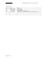
Revision History 
 

Revision 

Date 

Notes 

8-March-2018 

Initial Release 

A1 

21-June-2018 

Product release 

A2 

11-July-2018 

Added MR431 sensor diagrams 

A3 

17-Aug-2018 

Added System Loss Budget to MR430 Controller specifications 


Summary of Contents for MR430 Series

Page 1: ...44 843 4020 FX 41 44 843 4039 support micronor com www micronor com Notice of Proprietary Rights The design concepts and engineering details embodied in this manual which are the property of MICRONOR...

Page 2: ...sor System Page 2 of 50 Revision History Revision Date Notes A 8 March 2018 Initial Release A1 21 June 2018 Product release A2 11 July 2018 Added MR431 sensor diagrams A3 17 Aug 2018 Added System Loss...

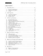
Page 3: ...Counter and Turn Counter Size 16 3 9 Multi Turn Operation 17 3 10 Battery Backup for Multi Turn Operation 17 3 11 SSI Interface 18 3 12 Voltage Output 20 3 13 Isolated Current Output 4 20mA 22 3 14 D...

Page 4: ...Location of RS485 Modbus RTU SSI and USB Connections 11 Figure 6 J3 Connector Pin Assignments 11 Figure 7 Plug for J3 Connector 11 Figure 8 Location of Recessed Home Button 13 Figure 9 Block Diagram o...

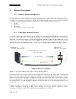
Page 5: ...lines within high magnetic fields MRI or explosive atmospheres This innovative product measures absolute angular position from 0 to 360 with 13 bit resolution and distances up to 100 feet Figure 1 Mic...

Page 6: ...s Multiple interfaces built in into one unit o SSI Interface o Modbus RTU via RS422 RS485 serial interface o USB Interface o Two Scalable Analog Position Outputs 10V and 4 20mA o One Programmable Digi...

Page 7: ...this procedure may affect your claim for compensation 2 3 Standard Contents MR431 Sensor MR431 Sensor Device with customer specified POF pigtail length Test Protocol Sheet Instruction Manual this docu...

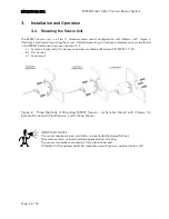
Page 8: ...awing in Section 9 2 a Synchro clamps set of 3x clamps and screw available as Micronor P N MR431 1101 b Flat washers c Face mount Figure 2 Three Methods of Mounting MR431 Sensor a Synchro Mount with C...

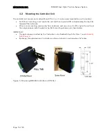
Page 9: ...by bending the clip tabs toward of the enclosure When screw mounting remove clip from enclosure and use screws to affix clip to the wall and then clip enclosure onto the plastic clip Both mounting sc...

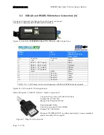
Page 10: ...is programmable via this interface or the USB interface Standard Baud rate is 57 600 1 Stop Bit No Parity The default Common Device Address is 235 The USB interface is a serial FTDI Virtual Communica...

Page 11: ...240 10P C 50 Digikey P N H11343 ND Mouser P N 798 324010PC50 Recommended Cable Tensility International P N 30 00534 Digikey P N T1355 5 ND Micronor P N MR430 99 01 available separately is a pre assemb...

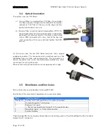
Page 12: ...two POF fibers terminate into a special purpose connector This connector end is polished and must be protected from scratches and contamination This connector is a service connector only and it should...

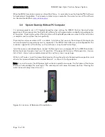
Page 13: ...the analog or SSI outputs do not require specific programming on site especially if the MR430 controller was pre configured for the customer s application at the factory or the customer is using the d...

Page 14: ...ch keeps track of the full turns of the sensor while the unit is powered up and the sensor is connected with the fiber optic link Absolute single turn position 13 bits and turn counter 12 bits combine...

Page 15: ...Output is a fully isolated 4 20mA loop powered output It has three programmable operating modes plus scaling over the full range of 25 bits Digital to analog output resolution is 13 bits The Voltage...

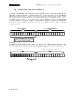
Page 16: ...lled by the user programmable Turn Counter variable This number defines how many bits deep the turn counter is counting until it rolls over back to zero Please note there are no negative position numb...

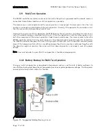
Page 17: ...her movement of the sensor is possible Under these circumstances the user may elect to have the MR430 controller restore the turns upon power on To safeguard against erroneous position restoration the...

Page 18: ...ot sure how to set the SSI baud rate leave it at the lowest setting of 25k baud this setting will work fine in most applications Reading position packets at higher than 4 kHz is not recommended as the...

Page 19: ...the transmission of complete data word 3 i e LSB is transmitted and an additional rising edge of the clock sets the clock line to go HIGH The data line is set to low and remains there for a period of...

Page 20: ...around occurs regardless of the Turn Mask setting Figure 14 Mode 2 Voltage Output MODE 2 lets the user program the output voltage based on a scale value The output is 0 when the position is 0 and wil...

Page 21: ...s then equal to the scale value and the voltage output will be 0V When the sensor turns CCW the voltage will start going negative and vice versa when the sensor turns CW the voltage will go positive A...

Page 22: ...are three selectable output modes Mode 0 OFF current is less then 300uA Mode 1 Single turn 4mA to 20mA Mode 2 Scalable 4mA to 20mA Figure 17 Isolated 4 20mA Connection Figure 18 Mode 1 Current Output...

Page 23: ...n The Countmax is then 2n The wrap point Pw is determined based on the formula above It is the midpoint between the un used range In ZapView select page Current Output MODBUS commands Address Registe...

Page 24: ...oint_ON and then define the point where the output should turn OFF again Should the output be inverted reverse the position points of the two entries and the output will switch at the same position bu...

Page 25: ...the Modbus To access these functions and to familiarize yourself with the functionality of the MR430 controller we recommend to use ZapView software which is supplied with the unit To run ZapView you...

Page 26: ...e may be connected directly to a PC Computer via standard RS232 and DB9 connector In that case the maximum baud rate is 57 600 The MR232 1 Interface cable converts the RS232 signals to the RS485 compa...

Page 27: ...tion MODBUS information can be obtained at www Modbus com What Is ZapView 430 Setup Software MICRONOR provides ZapView a user friendly setup program free of charge along with the purchase of the MR430...

Page 28: ...e Description 0x000 0x001 System Status 1 n a Returns the system status num register 1 reads status only num register 3 reads status position num register 4 reads status position angle num register 5...

Page 29: ...x137 Turn Counter 1 0 11 Depth of Turn Counter in binary increments 2n User sets this value depending how far the turn counter should count until resetting to 0 again Example n 3 Maximum Position read...

Page 30: ...urrent Mode 1 0 2 Defines the output mode for the current output 0 OFF current is 300uA 1 Single Turn 4 to 20mA 2 Multi Turn 4 to 20mA 0x205 0x206 Current Scale 2 0 MaxCount Establishes the scale used...

Page 31: ...Internal Supply Voltage 12V Updated only at Power ON 0x303 0x304 24V Power Supply 1 n a External applied Voltage 24V nominal Updated only at Power ON 0x304 0x305 n a 1 n a 0x305 0x306 n a n a 0x306 0x...

Page 32: ...egister If another error is pending then the status register will reflect that new value in queue 0x005 0x006 Clear Error Count Table Resets error table counters to 0 Same as in power up MODBUS Messag...

Page 33: ...ommunication Errors Communication errors are flagged by the underlying Modbus drivers However Modbus standard does not specify a data integrity test This is where the MR430 allows the user to query th...

Page 34: ...button once and wait and check if the error indication Because once the error is cleared the button will assume it s normal function as a Zero Point switch Some errors are cleared as soon as normal op...

Page 35: ...e or recycle Power Blink 5x code 259 EEPROM Checksum Low Bank checksum failure low bank 1 One set of data in EEPROM shows a bad checksum Firmware automatically corrects the error n a n a 260 EEPROM Ch...

Page 36: ...or The sensor makes a position measurement every 850 s This error indicates that an invalid position reading has occurred binary code on the disk allows for error checking 1 This error may occur when...

Page 37: ...rong Register Count The register count in your command did not match the length of requested register 1 Check your software for correct register addressing See user manual with address table Note This...

Page 38: ...esiding in the Status stack The remaining 15 bits indicate the number of errors that occurred since power was applied to the unit The user may clear all error counters by issuing Function Call FC5 coi...

Page 39: ...NOR INC MR430 Fiber Optic Position Sensor System Page 39 of 50 Y N T1 1024 T1 1024 Inc T1 Inc T2 NewE rror Log Error 1024 Clear New Error T2 5 6000 Log Error 56000 Reset T1 Reset T2 N N N T2 56k N Y Y...

Page 40: ...red products are warranted for the balance of the original warranty period or at least 90 days Limitations of Warranty This warranty does not apply to defects resulting from unauthorized modification...

Page 41: ...supply shall be current limited to 200mA Interface Update Rate Angular Speed 230 radians second or 2200 RPM for accurate position reporting Update Rate 1 17 kHz 850 s Reporting Delay SSI Maximum 800...

Page 42: ...Atmosphere Inherently Safe Simple Mechanical Device EX Classification Inherently safe simple mechanical device when used with MR430 1 Controller IEC Ex EPL Mb Gb Gc Db Dc MR Attributes ACR Guidance Do...

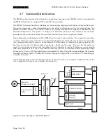
Page 43: ...System The functional block diagram shows the two main components The Sensor is connected by a duplex fiber optic cable The Transmit fiber guides an optical pulse from a red LED to the position sensor...

Page 44: ...MR430 Fiber Optic Position Sensor System Page 44 of 50 9 Mechanical Reference Drawings These reference drawings can be found on the following pages 9 1 MR430 1 Controller 9 2 MR431 Sensor 9 3 MR439 M...

Page 45: ...1 114 60 4 51 32 1 26 SMA KEYED INPUT CONNECTOR BARE FIBER SOURCE CONNECTOR J1 89 10 3 51 MINIMUM REQUIRED DISTANCE FOR FIBER OPTIC CONNECTION 3 5 89 UNIT MOUNTS ONTO STANDARD 35MM DIN RAIL 63 50 2 50...

Page 46: ...CONFIDENTIAL NOTES UNLESS OTHERWISE SPECIFIED SHEET WWW MICRONOR COM 805 389 6600 C B 1 OF 4 2 1 24 6 97 2 4 09 1 55 06 2 20 09 8 31 15 7 62 4 98 20 5 98 236 3X 4 40 UNC 2B 25 MIN 6 4MM 19 05 750 25 9...

Page 47: ...AS A WHOLE WITHOUT THE WRITTEN PERMISSION OF MICRONOR INC IS PROHIBITED PROPRIETARY AND CONFIDENTIAL NOTES UNLESS OTHERWISE SPECIFIED SHEET WWW MICRONOR COM 805 389 6600 C B 2 OF 4 2 1 33 02 1 30 BOL...

Page 48: ...OR AS A WHOLE WITHOUT THE WRITTEN PERMISSION OF MICRONOR INC IS PROHIBITED PROPRIETARY AND CONFIDENTIAL NOTES UNLESS OTHERWISE SPECIFIED SHEET WWW MICRONOR COM 805 389 6600 C B 3 OF 4 2 1 14 22 560 TH...

Page 49: ...PART OR AS A WHOLE WITHOUT THE WRITTEN PERMISSION OF MICRONOR INC IS PROHIBITED PROPRIETARY AND CONFIDENTIAL NOTES UNLESS OTHERWISE SPECIFIED SHEET WWW MICRONOR COM 805 389 6600 C B 4 OF 4 2 1 1 30 H...

Page 50: ...CONFIDENTIAL SHEET WWW MICRONOR COM 805 389 6600 C X1 1 OF 1 2 1 1 1m LENGTH REF HIROSE 3240 10P C 50 TO MR430 CONTROLLER TENSILITY PN 30 00534 1 CABLES ARE MADE NOMINALLY 0 1m LONGER THAN SPECIFIED...

Reviews: