21
Service Manual
www.microphase.eu
Dc
4.0
Internal adjustements
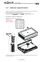
Dip switch
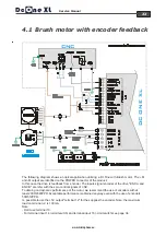
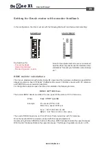
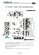
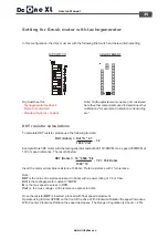
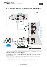
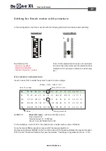
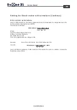
In the left-hand page for each chosen velocity feedback, is shown a typical connection with the notes
of wiring of the converter.
If changes need to made to the internal drive setting powering, please wait at least 30 seconds after
the power has been removed and the OK LED is off.
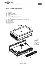
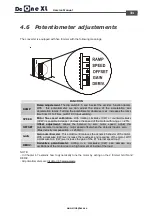
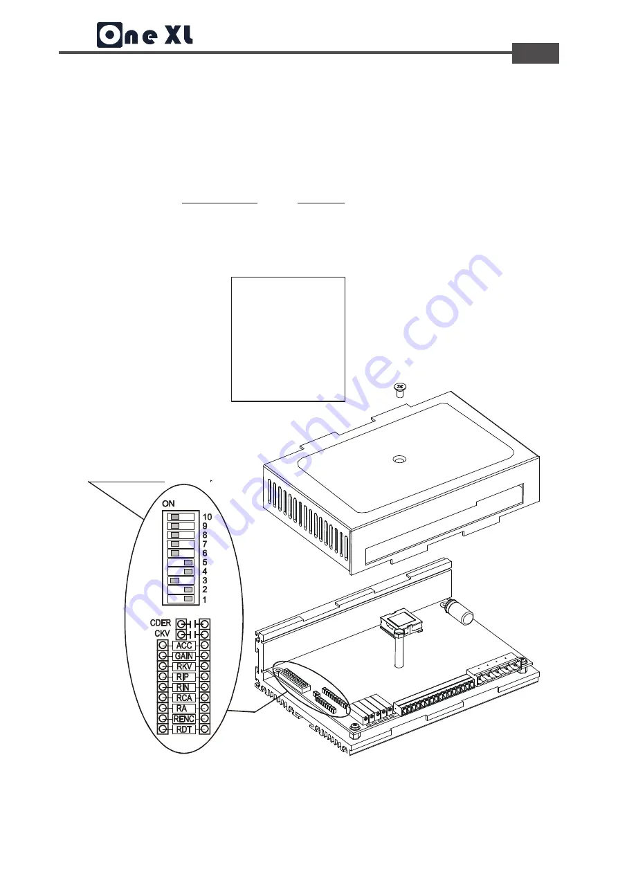
All of the personalizations are located inside of the DRIVE. (See figure above)
To gain access to the adjustment pads and the Dip switch, unscrew and remove the cover.
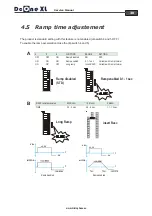
Dip swicth standard configuration
Dip 10: Closed (ON)
Dip 9: Closed (ON)
Dip 8: Closed (ON)
Dip 7: Closed (ON)
Dip 6: Closed (ON)
Dip 5: Open (OFF)
Dip 4: Open (OFF)
Dip 3: Closed (ON)
Dip 2: Open (OFF)
Dip 1: Open (OFF)
DIP SWITCH standard position are setting by
factory for:
- Encoder feedback
- Ramp time disabled
- Standard Dynamic constant

