Workstation 4 Setup Guide
2-19
What’s Inside?
Hardware Updates
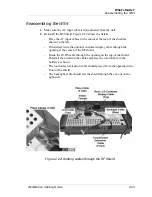
7. Replace RF shield cover as described on page 2-23.
8. Remove the logo plate from the cut-out at the rear of the top cover.
9. Place any excess cable inside the workstation.
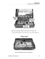
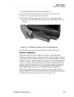
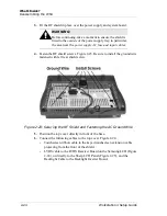
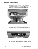
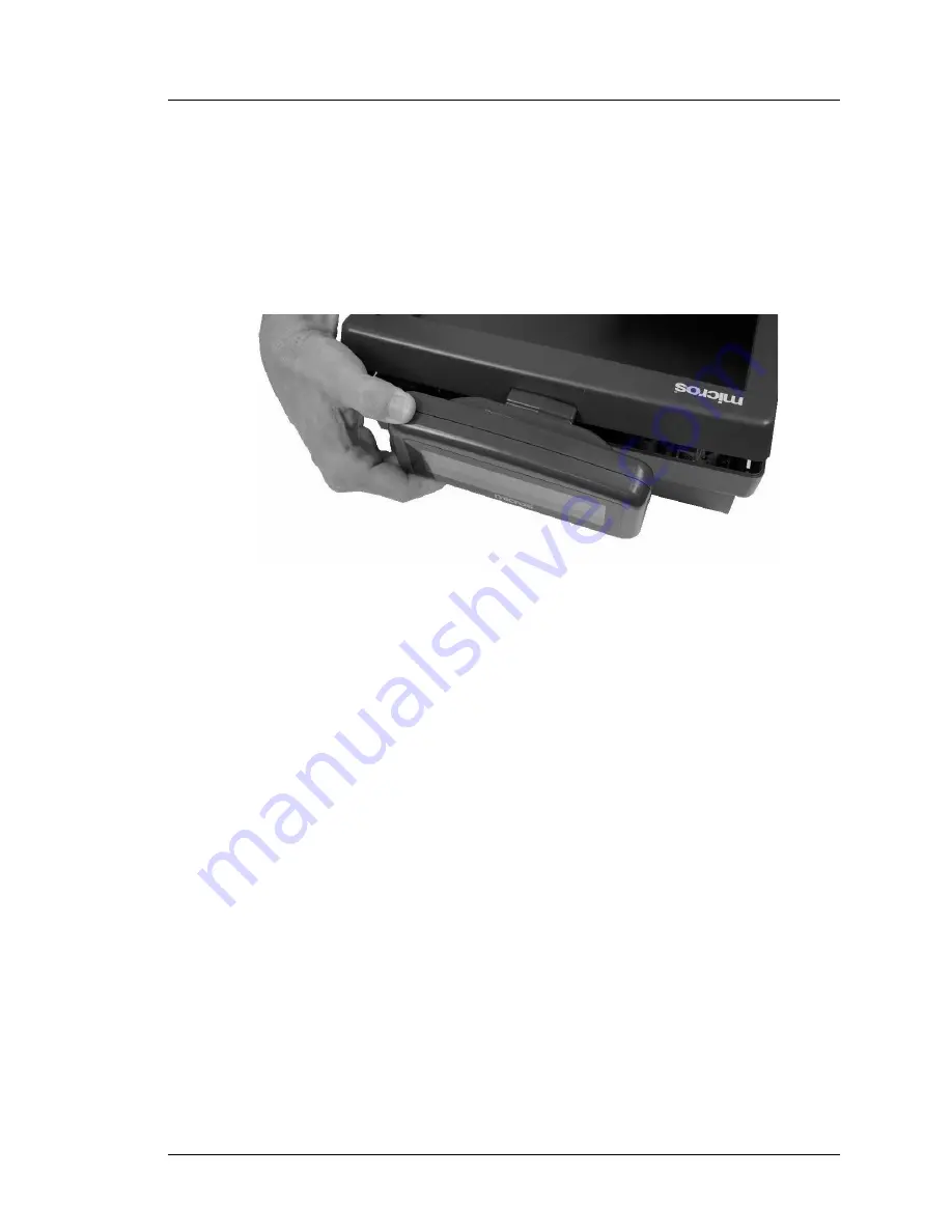
10. Orient the LCD assembly as shown in Figure 2-17, placing the hinge
assembly in the cut-out place the hinge in the cut-out and fit the top cover
to the base.
Figure 2-17: Installing the Rear LCD to the Workstation
11. Proceed to the next section and install the required software files.
Software Configuration
The WinCE image on a WS4 configured to run the e7 POS Application
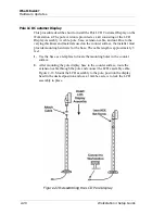
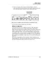
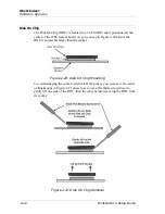
includes the necessary drivers to support the LCD Customer Display. However
the majority of WS4s currently in the field (as of September 2004) are running
the GR1.0 or GR1.1 software platform. If connected to a WS4 running GR1.0
or GR1.1, the LCD customer display will not function. An upgrade to GR1.2
or later is required to support the 2x20 VFD emulation mode. In addition, the
graphics features of the display are not yet supported by POS Applications
such as RES or L&E, however, the 2x20 VFD emulation is supported.
Instructions for upgrading the WS4 to the GR1.2 software platform can be
found in FB004-001. This document and the GR1.2 software platform files can
be found in the hardware support section at www.micros.com.
Summary of Contents for Workstation 4
Page 108: ...A 8 Workstation 4 Setup Guide Equipment Dimensions LCD Pole Display LCD Pole Display ...
Page 109: ...Workstation 4 Setup Guide A 9 Equipment Dimensions Cash Drawer Cash Drawer ...
Page 111: ...Workstation 4 Setup Guide A 11 Equipment Dimensions VFD Pole Display VFD Pole Display ...
Page 112: ...A 12 Workstation 4 Setup Guide Equipment Dimensions VFD Pole Display ...

