background image

6-12

MS-1 Scan Engine 

User Manual

Stop Trigger Character (Non-Delimited)

Stop Trigger Character (Non-Delimited)

Usage:

Useful in applications where different characters are required to end a 

read cycle.

Definition:

A single ASCII host serial trigger character that ends the read cycle and is 

not enclosed by delimiters such as 

<

 and 

>

.

Non-delimited 

Stop

 characters can be defined and will function according 

to the trigger event.
When defining 

Stop 

trigger characters, the following rules apply:

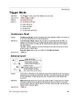
• In 

External Edge 

the MS-1 looks only for the 

Start

 trigger character

and ignores any 

Stop

 trigger character that may be defined.

• In 

External Level

 the 

Start

 trigger character begins the read cycle and

the 

Stop

 trigger character ends it. Note that even after a symbol has

been decoded and the symbol data transmitted, the MS-1 remains in

External Level

 trigger read cycle until a 

Stop

 character is received.

• In 

Serial Data and Edge 

trigger mode, either a 

Start

 trigger character

or a hardware trigger can start an edge trigger read cycle.

Serial Cmd:

<

K230,

stop trigger character

>

Default:

NUL

 (00 in hex) (disabled)

Options:

Two hex digits representing any ASCII character except 

XON

 and 

XOFF

.

Summary of Contents for MS-1

Page 1: ...MS 1 Scan Engine User Manual P N 84 000001 Rev A ...

Page 2: ...rein that we are using the names to the benefit of the trademark owner with no intention of infringement Disclaimer The information and specifications described in this manual are subject to change without notice Latest Manual Version For the latest version of this manual see the Download Center on our web site at www microscan com Technical Support For technical support e mail helpdesk microscan ...

Page 3: ...dow Placement 3 7 Tilt Skew and Pitch 3 8 Flex Cable 3 10 Chapter 4 Using ESP EZ Mode 4 2 Application Mode 4 3 Menu Toolbar 4 4 Autoconnect 4 12 View 4 14 Navigating in ESP 4 15 Send Receive Options 4 16 Chapter 5 Communications Communications by ESP 5 2 Communications Serial Commands 5 3 Host Port Connections 5 4 Host Port Protocol 5 5 Preamble 5 6 Postamble 5 7 Communications Mode 5 8 Keyboard M...

Page 4: ...7 PDF417 7 20 China Postal Code 7 21 Symbology Identifier 7 22 Chapter 8 Terminal Terminal Window 8 2 Find 8 3 Send 8 4 Macros 8 5 Terminal Window Menus 8 6 Chapter 9 Utilities Serial Utility Commands 9 2 Read Rate 9 3 Differences from Default 9 4 Firmware 9 5 Device Control 9 7 Default Reset Save 9 8 Reader Status Request 9 9 Hardware Default 9 10 Appendices Appendix A General Specifications A 2 ...

Page 5: ...S 1 Scan Engine The sections are presented in the order in which the MS 1 might be set up and made ready for operation Highlighting Serial commands highlighted command fields and default command settings are highlighted in rust bold Cross references and web links are highlighted in blue bold References to ESP its toolbar headings Communications Read Cycle Symbologies etc menu topics and other poin...

Page 6: ...es other than those specified herein may result in hazardous radiation exposure IMPORTANT The MS 1 is intended for connection to a UL listed direct plug in power unit marked Class II and rated 5 VDC at 3 5 Watts or greater if using electrical accessories European models must use a similarly rated Class I or Class II power supply that is certified to comply with safety standard EN 60950 WARNING LED...

Page 7: ...nsible for compliance could void the user s authority to operate the equipment The MS 1 has been tested for compliance with CE Conformité Européenne standards and guidelines and has been found to conform to applicable CE standards specifically the EMC requirements EN 55024 1998 A1 2001 A2 2003 ESD EN 61000 4 2 Radiated RF Immunity EN 61000 4 3 ENV 50204 EFT EN 61000 4 4 Conducted RF Immunity EN 61...

Page 8: ...garding accuracy or correctness Microscan does not specifically run any analysis on our raw materials or end product to measure for these substances The information provided in this certification notice is correct to the best of Microscan s knowledge at the date of publication This notice is not to be considered a warranty or quality specification Users are responsible for determining the applicab...

Page 9: ...bilities and to test symbol decode performance Detailed setup information for installing the MS 1 into your application can be found in the subsequent sections Step 1 Check Hardware 1 2 Step 2 Connect the System 1 3 Step 3 Install ESP 1 4 Step 4 Select Model 1 5 Step 5 Autoconnect 1 6 Step 6 Position the MS 1 Scan Engine 1 7 Step 7 Configure the MS 1 Scan Engine 1 8 Step 8 Save Configuration in ES...

Page 10: ...gine 32 bit LD 2 PCBA Demo Board Supports 32 bit MS 1 or legacy 16 bit MS 1 3 Two M1 6 x 35 x 4 mm screws button or pan head Philips drive stainless steel or corrosion resistant plating 4 Flex Strip FFC Jumper Cable contacts 12 0 5 mm center one side only 100 mm 3 mm length 5 USB Virtual COM cable RJ45 plug to USB 2 3 meters length 6 MS 1 Scan Engine Demonstration Guide Caution Be sure that all ca...

Page 11: ...5 end of the USB Virtual COM cable into the connector on the demo board If using mini USB Plug mini USB cable into mini USB connector at J1 5 Plug the USB end of the USB Virtual COM cable into the USB port on the host computer If using mini USB Plug mini USB cable into USB connector on host computer 6 Insert a 9V battery into the battery bay on the underside of the board If using mini USB or USB V...

Page 12: ...he prompts to install ESP from the Microscan Tools Drive 2 Click on the ESP icon to run the program Minimum System Requirements 233 MHz Pentium PC Windows 8 7 Vista or XP operating system 32 bit or 64 bit Internet Explorer 6 0 or higher 128 MB RAM or greater 160 MB free disk space 800 x 600 256 color display 1024 x 768 32 bit color recommended ...

Page 13: ...ick the button showing the MS 1 Scan Engine 2 Click OK Note You can also double click the MS 1 Scan Engine button to make your selection 3 Click Yes when this dialog appears Note If you need to select another model later click the Switch Model button near the top of the screen or use Model New Model in the menu toolbar ...

Page 14: ...ect RS 232 in the dialog shown below to communicate with the demo kit MS 1s that are sold in the standard 8 pack FIS 0001 800XG are in RS 232 by default Select RS 232 to communicate with the reader When a connection is established the green indicator in the status bar at the bottom right of the screen will be visible Important The MS 1 is in Continuous Read Mode by default For best connection resu...

Page 15: ...rom other sources including other readers Pitch the MS 1 or symbol at a minimum of 15 to avoid specular reflection the return of direct non diffused light Avoid excessive skew or pitch Maximum skew is 30 maximum pitch is 30 Note Code 39 is the default symbology enabled If you are uncertain of your symbology perform the following steps 1 Enable all symbologies using ESP 2 Enable Symbology Identifie...

Page 16: ...mmunication Click the Send Recv button to send or receive commands Click the Switch Model button to open the model menu or to return to a previous model Click the Parameters button to show the tabbed tree controls for Communication Read Cycle and Symbologies Click the Terminal button to display decoded symbol data and to send serial commands to the imager using text or macros Click the Utilities b...

Page 17: ...s activates all changes in current memory saves to the MS 1 for power on and saves the Communications Mode setting 1 Left click on the to expand the desired tree 2 Double click on the desired parameter and click once in the selection box to view options 5 Right click on the open screen and select Save to Reader to implement the command in the MS 1 4 Left click again on the open screen to complete ...

Page 18: ...1 10 MS 1 Scan Engine User Manual Save Changes in ESP ...

Page 19: ...MS 1 Scan Engine User Manual 2 1 2 Setup and Operation Contents This section describes the flex cable pin assignments Electrical Interface 2 2 Configuration 2 5 ...

Page 20: ...de Flex Cable Pin Host RS 232 TTL In Out 1 5V Power VCC In 2 TTL_RxD In 3 Trigger Input In 4 Power Enable In 5 TTL_TxD Out 6 TTL_RTS Out 7 GND 8 USB_D In Out 9 LED Engine Status Out 10 TTL_CTS In 11 Beeper Decode Indicator Out 12 USB_D In Out MS 1 Scan Engine MS 1 end 12 contacts Host end 12 contacts ...

Page 21: ...t system For firmware update use 3 Trigger In 0 Lighting on Scan engine reads decodes and sends information to host 1 Lighting off Scan engine stops reading decoding and transmitting 4 Power Enable In 0 Scan engine on 1 Scan engine off except during data transmission and when writing setup parameters to non volatile memory 5 TxD Out Serial output transmission to host system For firmware update use...

Page 22: ... cont 7 GND Ground 8 USB_D In Out USB data 9 LED Out CCD engine status display 10 CTS In Host authorizes scan engine to transmit on TxD line RTS CTS hardware protocol 11 Beeper Out Active symbol successfully decoded Low level inactive awaiting decode 12 USB_D In Out USB data ...

Page 23: ...sing ESP helps you understand the basic structure and elements of ESP which is the configuration software that you will use to set up the MS 1 for operation Communications explains how to set up communications between the MS 1 and a host Read Cycle explains the spatial and timing parameters associated with your application Symbologies describes the various symbol types that can be decoded by the M...

Page 24: ...2 6 MS 1 Scan Engine User Manual Configuration ...

Page 25: ...lation Contents This section describes how to integrate the MS 1 mechanically Mounting the MS 1 Scan Engine 3 2 Window Materials 3 3 Optical Components 3 5 Electrical Components 3 6 Window Placement 3 7 Tilt Skew and Pitch 3 8 Flex Cable 3 10 ...

Page 26: ...3 2 MS 1 Scan Engine User Manual Mounting the MS 1 Scan Engine Mounting the MS 1 Scan Engine Mechanical Dimensions Recommended screw torque 3 kgf ...

Page 27: ...or ultrasonic welding No matter what window material you choose do not tint the window Because the MS 1 is a CCD scan engine an anti reflective coating is not necessary Spectral Transmission 85 minimum from 640 to 690 nm Material Glass Acrylic Acrylic has superior optical qualities and relatively good impact resistance at a low initial cost However acrylic has surface sensitivity to environmental ...

Page 28: ... custom optics html Dontech Inc http www dontech com TSP Inc http www tspinc com Window Fabrication Companies Nelson Nameplate http www nelsonusa com Cadillac Plastic http www cadillacplastic com Reading Plastic Fabricators http www readingplastic com G S Supplies http www gssupplies com Laurel Industries http www laurelindustries com ...

Page 29: ... achieve optimal performance damage to optical components must be avoided Avoid scrubbing the optical surface and never wipe the optical surface with a dry cloth You may spray glass cleaner on a non abrasive cloth and then gently wipe the module window Do not touch the optical components ...

Page 30: ... from electrostatic discharge by minimizing physical contact with the integrated circuits and other electrical components in the scan engine Keep the scan engine in the anti static case until you are ready to install it in your device Use grounding wrist straps when handling the scan engine ...

Page 31: ...MS 1 Scan Engine User Manual 3 7 Installation Window Placement The function of the window is to keep dust and other particulates out of the host case and to protect the scan engine ...

Page 32: ...tch Tilt Skew and Pitch Be aware of the tolerance for the tilt pitch and skew of the symbol you are trying to scan Symbol EAN 13 digits 37 mm 0 33 mm 13 mil 0 39 mm 15 6 mil R R or 25 mm R or 25 mm d 90 mm 120 mm PCS 0 9 printed on photographic paper ...

Page 33: ...ces bar width and affects high density symbols more than low or medium density symbols Decoding may be possible with a skew angle of up to 65 degrees Pitch Pitch reduces bar height Decoding may be possible with a pitch angle of up to 75 degrees Reducing pitch increases decoding efficiency A low pitch angle 2 3 degrees minimum is helpful because it prevents specular reflection Tilt axis Skew axis P...

Page 34: ...small screwdriver or other pointed object to extend the clip so that the end of the flex cable can be inserted 2 Remove the flex cable carefully 3 Install a new flex cable as required The flex cable connectors must be in direct contact with the scan engine connectors MS 1 Scan Engine MS 1 end 12 contacts Host end 12 contacts ...

Page 35: ...specific element of MS 1 operation For example the Communications menu shows a Host Port Connections option and then a list of the sub options Baud Rate Parity Stop Bits and Data Bits Each of these sub options is configurable by using dropdown menus Graphic User Interfaces MS 1 settings can be configured using such point and click tools as radio buttons zoom in zoom out sliders spin boxes check bo...

Page 36: ...MS 1 in relation to a test symbol and also features an Autodiscriminate function that automatically enables all symbologies Enter App Mode to access configuration trees and other setup features If you are unsure what type of symbology you are using click Autodiscriminate to enable all symbologies ...

Page 37: ...pear in the same position to allow easy switching between these primary modes Note See the corresponding sections of this manual for specific information on any of the views or modes mentioned above Menu toolbar Click this icon to return to EZ Mode Click the Parameters icon to return to full App Mode view from Terminal or Utilities Click on tabs in this row to access configuration trees like the o...

Page 38: ...the same file is selected under Open Important When you save menu changes to your hard drive these changes are not saved to the MS 1 The illustration below shows how settings can be saved and received between ESP and the MS 1 and ESP and the host hard drive Import Export Import converts the ASCII settings from a text file to ESP configuration settings Export converts the active ESP configuration s...

Page 39: ...ed by ESP When you choose a different model the connection to your present model will be terminated To connect to another model select New Model choose a new model from the pop up menu that appears and click OK Note When you save an ESP file you are saving the settings of all the models defined in that file ...

Page 40: ...e model menu displaying all supported readers Show Connect Prompt At startup displays the Would you like to connect to the MS 1 prompt Receive After Connect At startup loads the MS 1 s settings into ESP This is not recommended if you want to preserve your ESP settings for future use Skip EZ Mode At startup skips EZ Mode and opens directly in App Mode Enable Send and Save as Factory Settings This o...

Page 41: ...end a trigger character select F2 then in the Ctrl row enter trigger character and click OK Then whenever the Ctrl F2 keystroke is pressed the trigger character will start the read cycle Note The F1 key is reserved for opening ESP Help and the F3 key is reserved for the Find Next function Change Font Allows you to modify the font used for decode data received from the MS 1 on the Terminal screen C...

Page 42: ...ialog allows you to set the size of user created symbols Sizing Information Sets the bar width or module width in mils or thousandths of an inch of user created symbols Example A bar width of 14 is 0 014 inches Caption Allows you to define and position a human readable caption for the symbol you create ...

Page 43: ...ON with Autoconnect Sends an XON Begin Transmission command to the MS 1 before starting the Autoconnect routine Ask to Save ESP File when Quitting When enabled prompts the user to save a esp file when ending a session The esp file will be saved in the location of your choice ...

Page 44: ...ect to Reader via TCP IP When enabled shows a TCP IP option on the Select Protocol dialog Note This option should only be selected if you intend to connect using an Ethernet adapter Use Default Storage Location When enabled automatically stores data in ESP s Application Data folder ...

Page 45: ...you type in the Model Memo field will appear in a context sensitive text box whenever your cursor hovers over the Model Memo item on the Options menu Memos created in Model Memo are specific to the model enabled when the message was created Note Memos must be saved in a esp file if you want them to available in your next session If you do not save your current session any memos that you have enter...

Page 46: ...establish a connection between the MS 1 and the host If your communications port is not the default COM1 use the dropdown menu to change your port When you are connected you will see the green connection indicator in the status bar at the bottom right of your screen Once you have chosen the correct port click Start to connect ...

Page 47: ...ct cont If your RS 232 host settings cannot be changed to match the MS 1 s settings Click Connect on ESP s menu toolbar and then select Connect on the dropdown menu When the Connection Settings dialog appears check the Force Connect box and click Connect ...

Page 48: ...ser Manual View View The View menu allows you to move quickly between interfaces without using the icon buttons on the App Mode toolbar Notice that each menu item corresponds with the icon buttons at the top of the ESP window ...

Page 49: ... click in the selection box to view options 3 Place your cursor in the selection box scroll down to the setting you want to change and single click the setting 4 Left click again on the open screen to complete the selection 5 Right click on the open screen and select Save to Reader to implement the command in the MS 1 You can send the command without saving it you can send and save the command sim...

Page 50: ...tings and save them as a file for future use For example if your MS 1 has settings that you do not want to change choosing Yes would allow you to load those settings to ESP and save them in an ESP file for later retrieval Receiving the MS 1 s settings will also assure that you will not be subsequently saving any unwanted changes that you or someone else has made previously in ESP Saving Send No Sa...

Page 51: ...ands These are commands that may be in your MS 1 s firmware but are not included in or are different from your current version of ESP When exceptions are present the Exceptions button will appear to the right of the other mode buttons Communication Read Cycle Symbologies When no exceptions are present the button will disappear You can edit exception commands by double clicking on them and changing...

Page 52: ...4 18 MS 1 Scan Engine User Manual Send Receive Options ...

Page 53: ...am configuration changes can be made in the ESP tree controls and then sent and saved to the MS 1 The user can also send serial commands to the MS 1 via ESP s Terminal Communications by ESP 5 2 Communications Serial Commands 5 3 Host Port Connections 5 4 Host Port Protocol 5 5 Preamble 5 6 Postamble 5 7 Communications Mode 5 8 Keyboard Mapping 5 9 USB Keyboard Key Codes 5 10 ...

Page 54: ...ns by ESP Communications by ESP Click this button to bring up the App Mode view then click the Communication tab To open nested options single click the To change a setting double click the setting and use your cursor to scroll through the options ...

Page 55: ...ort Connections K100 baud rate parity stop bits data bits Keyboard Mapping K116 keyboard layout caps lock mode number lock Communications Mode K117 communications mode Host Port Protocol K140 protocol Preamble K141 status preamble character s Postamble K142 status postamble character s ...

Page 56: ...ry to match host setting Definition An error detection routine in which one data bit per character is set to 1 or 0 so that the total number of bits in the data field is either even or odd Serial Cmd K100 baud rate parity stop bits data bits Default Even Options 0 None 1 Even 2 Odd Usage Only changed if necessary to match host setting Definition One or two bits added to the end of each character t...

Page 57: ...lt Point to Point Options 0 Point to Point 1 Point to Point with RTS CTS Usage Used only with RS 232 or RS 422 Definition Standard Point to Point requires no address and sends the data to the host whenever it is available without a request or handshake from the host Serial Cmd K140 0 Usage An MS 1 initiates a data transfer with an RTS request to send transmission The host when ready responds with ...

Page 58: ...wn line Definition Defines a one to four character data string that can be added to the beginning of the decoded data Serial Cmd K141 status preamble character s Default Disabled Options 0 Disabled 1 Enabled within any protocol Serial Cmd K141 status preamble character s Default M carriage return Options To enter control characters within a serial command hold down the Ctrl key while typing the de...

Page 59: ...ine Definition Allows the user to enable or disable up to four postamble characters that can be added to the end of the decoded data Serial Cmd K142 status postamble character s Default Enabled Options 0 Disabled 1 Enabled within any protocol Serial Cmd K142 status postamble character s Default M J carriage return line feed Options To enter control characters within a serial command hold down the ...

Page 60: ...eader communication Important You must send a Zp to the reader or Send and Save Including Factory from ESP after changing this parameter Note If you are using an MS 1 Demo Kit the Communications Mode default is USB Virtual COM Serial Cmd K117 communications mode Default RS 232 Options 0 RS 232 1 USB Native HID 2 USB Virtual COM ...

Page 61: ...lt English U S Options 0 English U S 1 English UK 2 German 3 French 4 Japanese 5 Spanish 6 Italian 7 Universal 8 Swiss 9 Czech Definition Allows the user to set caps lock Serial Cmd K116 keyboard layout caps lock mode number lock Default Off Options 0 Off 1 On 2 Free Definition Allows the user to set number lock Serial Cmd K116 keyboard layout caps lock mode number lock Default Alphanumeric Option...

Page 62: ...rl C D5 F6 FA Left Win down 04 Ctrl D D6 F7 FB Left Win up 05 Ctrl E D7 F8 FC Right Win down 06 Ctrl F D8 F9 FD Right Win up 07 Ctrl G D9 F10 08 Ctrl H DA F11 09 Ctrl I DB F12 0A Ctrl J DC HOME 0B Ctrl K DD END 0C Ctrl L DE RIGHT Arrow 0D Ctrl M DF LEFT arrow 0E Ctrl N E0 UP arrow 0F Ctrl O E1 DOWN arrow 10 Ctrl P E2 Page Up 11 Ctrl Q E3 Page Down 12 Ctrl R E4 TAB 13 Ctrl S E5 Back TAB 14 Ctrl T E...

Page 63: ...rameters Read Cycle by ESP 6 2 Read Cycle Serial Commands 6 3 MS 1 Read Cycle Overview 6 4 Number of Symbols 6 5 Time Between Identical Decodes 6 6 Trigger Mode 6 7 Continuous Read 1 Output Emulation 6 9 Serial Trigger Character Delimited 6 10 Start Trigger Character Non Delimited 6 11 Stop Trigger Character Non Delimited 6 12 No Decode Timeout 6 13 Decodes Before Output 6 14 No Read Message 6 15 ...

Page 64: ...e by ESP Read Cycle by ESP To change a setting double click the setting and use your cursor to scroll through the options Click this button to bring up the App Mode view and then click the Read Cycle tab To open nested options single click the ...

Page 65: ...r No Decode Timeout K220 0 seconds Decodes Before Output K221 decodes before output Number of Symbols K222 number of symbols Start Trigger Character K229 start character Stop Trigger Character K230 stop character Time Between Identical Decodes K503 time between identical decodes Shutter Speed K544 shutter speed No Read Message K714 status No Read message ...

Page 66: ...tive decodes The following conditions also apply 1 In Single symbol mode a read cycle ends only on a decode falling trigger or timeout 2 In Multiple symbol mode the read cycle begins on a triggered event but starts over after any symbol has been decoded 3 There is no new trigger feature 4 There is no timeout for External Level mode 5 There is no Continuous Read 1 Output setting in Trigger Mode but...

Page 67: ...ngle the read cycle ends when one symbol is decoded and output When Number of Symbols is set to Multiple all decoded symbol data for both the same and different symbols is output while the read cycle is active and or no timeout has occurred If set to Multiple and Time Between Identical Decodes is less than the decode time typically about 4ms the same symbol data can be output multiple times Defini...

Page 68: ...e symbol operations When used in conjunction with Number of Symbols set to Multiple Time Between Identical Decodes can be set so that more than one symbol can be read within a read cycle Definition Determines the length of time that the MS 1 will wait before it outputs the same symbol s data a second time Serial Cmd K503 time between identical decodes Default 0 Options 0 to 2550 ms ...

Page 69: ...nds that require responses when symbol data is transmitted Note No Read options have no affect on Continuous Read Serial Cmd K200 0 Usage This mode is effective in an application where the speeds of the conveying apparatus are variable and the time the MS 1 spends reading each object is not predictable It also allows the user to determine if a No Read has occurred Definition External Level allows ...

Page 70: ...en the object is in the field of view It is also useful in determining if a No Read has occurred Definition In Serial Data the MS 1 accepts an ASCII character from the host or controlling device as a trigger to start a read cycle A Serial Data trigger behaves the same as an External Edge trigger Serial commands are entered inside angle brackets as shown here t Serial Cmd K200 4 Usage Serial Data a...

Page 71: ...tion It is also effective in applications where the objects are presented by hand The MS 1 does not offer this feature but it can be emulated by following the steps described below Definition In Continuous Read 1 Output Emulation the trigger must be active grounded for as long as the MS 1 needs to be scanning symbols The MS 1 will only output symbol data once while that symbol remains in the MS 1 ...

Page 72: ...trigger is considered an online host command and requires the same command format as all host commands It must be entered within angle bracket delimiters or in the case of non delimited triggers it must define individual start and stop characters Serial Cmd K201 serial trigger character Default GS Options Any single ASCII character including control characters except NUL 00 in hex an existing host...

Page 73: ...rnal Edge the MS 1 looks only for the Start trigger character and ignores any Stop trigger character that may be defined In External Level the Start trigger character begins the read cycle and the Stop trigger character ends it Note that even after a symbol has been decoded and the symbol data transmitted the MS 1 remains in External Level trigger read cycle until a Stop character is received In S...

Page 74: ...ly In External Edge the MS 1 looks only for the Start trigger character and ignores any Stop trigger character that may be defined In External Level the Start trigger character begins the read cycle and the Stop trigger character ends it Note that even after a symbol has been decoded and the symbol data transmitted the MS 1 remains in External Level trigger read cycle until a Stop character is rec...

Page 75: ...which there are no decodes not the time since the trigger was activated That is if the MS 1 continues to decode symbols presented to it it will not exit the read cycle unless the time between decodes exceeds the time set in No Decode Timeout For Level trigger mode the read cycle ends when the trigger falls or when a symbol is decoded and output in Single symbol mode Usage Useful in tightly control...

Page 76: ... during the read cycle a No Read message will be output Note Higher Decodes Before Output settings will decrease the throughput rate Usage Useful for increasing the reliability of decodes for symbologies that do not have internal error checking Definition The number of decodes required per symbol before its data is sent Requires the MS 1 to decode a symbol successfully a designated number of times...

Page 77: ... applications where the host needs serial verification that a symbol has not been read Definition When enabled and if no symbol has been decoded before timeout or the end of the read cycle the No Read message will be transmitted to the host Serial Cmd K714 status No Read message Default Enabled Options 0 Disabled 1 Enabled Definition Any combination of ASCII characters can be defined as the No Rea...

Page 78: ... not be changed unless they are being increased to accomodate a fast line speed in a dynamic application Usage Faster shutter speeds may be necessary in faster moving applications Slower shutter speeds are useful in slower lower contrast applications Definition Shutter speed is the amount of time that the sensor is exposed to light Serial Cmd K544 shutter speed Default Automatic Options 0 Automati...

Page 79: ...information http www aimglobal org standards aimpubs asp http barcodes gs1us org dnn_bcec Default aspx tabid 82 Symbologies by ESP 7 2 Symbologies Serial Commands 7 3 Code 39 7 4 Codabar 7 6 Interleaved 2 of 5 7 8 Code 128 EAN 128 7 10 Code 93 7 11 GS1 DataBar RSS 7 12 MSI Code 7 13 Plessey Code 7 14 Industrial 2 of 5 7 15 UPC EAN 7 17 PDF417 7 20 China Postal Code 7 21 Symbology Identifier 7 22 ...

Page 80: ...s by ESP Symbologies by ESP To change a setting double click the setting and use your cursor to scroll through the options Click this button to bring up the App Mode view and then click the Symbologies tab To open nested options single click the ...

Page 81: ...h 1 1 0 application record separator character Code 93 K475 status 0 minimum symbol length PDF417 K476 status DataBar 14 RSS 14 K482 status DataBar Limited RSS Limited K483 status DataBar Expanded RSS Expanded K484 status MSI Code K486 status check character mode check character output status 0 minimum symbol length Plessey Code K487 status check character output status 0 minimum symbol length Ind...

Page 82: ...e as successful Serial Cmd K470 status check character status check character output status 0 0 minimum symbol length full ASCII set Default Disabled Options 0 Disabled 1 Enabled Usage Check Character Output Status when added to the symbol provides additional data security Definition When enabled the check character is read and output along with the symbol data When disabled symbol data is output ...

Page 83: ...ol length full ASCII set Default 0 Options 0 to 32 Usage Must be enabled when reading characters outside the standard character set 0 9 A Z etc The user must know in advance whether or not to use the Full ASCII Set option Since Full ASCII Set requires two code words to encode one character it is less efficient Definition Standard Code 39 encodes 43 characters zero through nine capital A through ca...

Page 84: ...present in the data output of the decoded symbol When disabled the start and stop characters will not be present in the data output of the decoded symbol Note Because the start and stop characters are included as part of the data the characters must be included as part of the length in a fixed length mode of operation Serial Cmd K471 status 0 start stop output status 0 symbol length status symbol ...

Page 85: ...ations on decoded Codabar symbols When set to Modulus 16 the MS 1 will perform a Modulus 16 check character calculation on the symbol If the symbol does not pass this calculation it will not be decoded Serial Cmd K471 status 0 start stop output status 0 symbol length status symbol length check character status check character output Default Disabled Options 0 Disabled 1 Enabled Modulus 16 Definiti...

Page 86: ...aved spaces representing the second character A check character is highly recommended Serial Cmd K472 status check character status check character output status symbol length 1 symbol length 2 Default Disabled Options 0 Disabled 1 Enabled Usage This option is not typically used but it can be enabled for additional security in applications where the host requires redundant check character verifica...

Page 87: ...only be decoded if it is equal to Symbol Length 1 Examples Usage Useful in applications where I 2 5 symbols of a specific length are required Definition The Symbol Length 1 field is one of two fields against which the decoded symbol is compared before accepting it as valid or rejecting it Serial Cmd K472 status check character status check character output symbol length 1 symbol length 2 Default 1...

Page 88: ...aracter Default Disabled Options 0 Disabled 1 Enabled Usage Minimum Symbol Length helps prevent truncations and increases data integrity by ensuring that only one symbol length will be accepted Definition This specifies the exact number of characters that the MS 1 will recognize this does not include start stop and check characters The MS 1 ignores any symbol not having the specified length Serial...

Page 89: ...paces Serial Cmd K475 status 0 minimum symbol length Default Disabled Options 0 Disabled 1 Enabled Definition Specifies the minimum number of characters that the MS 1 will recognize not including the start and stop check characters The MS 1 ignores any symbol smaller than the specified length Note When setting Minimum Symbol Length to any value other than 0 add 1 to account for a reserved space Fo...

Page 90: ...s it can read omnidirectionally if printed in full height or horizontally if height truncated for small marking Serial Cmd K482 status Default Disabled Options 0 Disabled 1 Enabled Usage DataBar Limited is designed to be read by laser scanners and CCD readers It is not recommended for omnidirectional slot scanners Definition Encodes a smaller 14 digit symbol 74 modules wide that is not omnidirecti...

Page 91: ...ulus 10 calculation by default It can also be set to perform a Double Modulus 10 calculation Serial Cmd K486 status check character mode check character output status 0 minimum symbol length Default Modulus 10 Options 1 Modulus 10 2 Double Modulus 10 Definition When this field is enabled the MS 1 will output the check digit with symbol data When disabled the MS 1 will not output the check digit wi...

Page 92: ...aracter output status 0 minimum symbol length Default Disabled Options 0 Disabled 1 Enabled Definition When this field is enabled the check character will be output with symbol data When disabled the check character will not be output with symbol data Serial Cmd K487 status check character output status 0 minimum symbol length Default Disabled Options 0 Disabled 1 Enabled Definition This field spe...

Page 93: ...th 1 symbol length 2 Default Disabled Options 0 Disabled 1 Enabled Definition When this field is enabled a check character is added Serial Cmd K488 status check character status check character output status format symbol length 1 symbol length 2 Default Disabled Options 0 Disabled 1 Enabled Definition When this field is enabled the check character will be output with symbol data When disabled the...

Page 94: ...ed number of characters Because Industrial 2 of 5 is a continuous symbology it is prone to substitution errors Therefore a symbol length must be defined and a symbol must contain an even number of characters Serial Cmd K488 status check character status check character output status format symbol length 1 symbol length 2 Default 10 Options 0 to 32 Definition This field specifies the number of char...

Page 95: ...ions When enabled the MS 1 will read UPC A symbols Serial Cmd K489 UPC A status UPC E status EAN 8 status EAN 13 status supplementals required supplemental 2 status supplemental 5 status UPC A as EAN 13 UPC E as UPC A EAN 8 as EAN 13 Default Enabled Options 0 Disabled 1 Enabled Definition This field is enabled by default and will decode all UPC E symbols Serial Cmd K489 UPC A status UPC E status E...

Page 96: ...tandard UPC or EAN symbol Serial Cmd K489 UPC A status UPC E status EAN 8 status EAN 13 status supplementals required supplemental 2 status supplemental 5 status UPC A as EAN 13 UPC E as UPC A EAN 8 as EAN 13 Default Disabled Options 0 Disabled 1 Enabled Definition A 2 character symbol appended to the main symbol Serial Cmd K489 UPC A status UPC E status EAN 8 status EAN 13 status supplementals re...

Page 97: ...bled 1 Enabled Definition When enabled UPC E will be transmitted as UPC A Serial Cmd K489 UPC A status UPC E status EAN 8 status EAN 13 status supplementals required supplemental 2 status supplemental 5 status UPC A as EAN 13 UPC E as UPC A EAN 8 as EAN 13 Default Disabled Options 0 Disabled 1 Enabled Definition When enabled EAN 8 will be transmitted as EAN 13 Serial Cmd K489 UPC A status UPC E st...

Page 98: ...ymbol with multiple fields of information that will be read at several stations along the way without reference to a database Definition A two dimensional multi row 3 to 90 continuous variable length symbology that has high data capacity for storing up to 2 700 numeric characters 1 800 printable ASCII characters or 1 100 binary characters per symbol Each symbol character consists of 4 bars and 4 s...

Page 99: ...s 0 Disabled 1 Enabled Definition When this field is enabled a check digit is added Serial Cmd K498 status check digit mode min length max length Default Disabled Options 0 Disabled 1 Enabled Definition Determines the minimum symbol length Serial Cmd K498 status check digit mode min length max length Default 11 Options 1 48 Definition Determines the maximum symbol length Serial Cmd K498 status che...

Page 100: ...mbologies the modifier is 0 Definition The Symbology Identifier is a standard prefix set of characters that identifies the symbol type When enabled the MS 1 analyzes and identifies the symbology and adds a three character identifying prefix to the data closed bracket character indicating the presence of a symbology identifier A C E I P M G F e A Code 39 C Code 128 EAN 128 E UPC EAN I Interleaved 2...

Page 101: ...MS 1 Scan Engine User Manual 8 1 8 Terminal Contents This section describes the Terminal window and Macro functions in ESP Terminal Window 8 2 Find 8 3 Send 8 4 Macros 8 5 Terminal Window Menus 8 6 ...

Page 102: ...een also displays symbol data or information from the MS 1 You can right click on the screen to bring up a menu of several options for managing data in the Terminal view Click this button to display the Terminal view Click on desired Macro to run Click on arrows to Add Macro Remove Macro or Edit Macro Macroslisted on this bar Clear screen Terminal screen Type text here to find matching text in the...

Page 103: ...ta from a series of symbols has been sent to the Terminal and you want to determine if a particular symbol whose data begins with ABC has been decoded 1 Type ABC into the Find field 2 Press Enter The first instance of ABC will be highlighted in the Terminal window 3 Click the Find button to the left of the text field to locate additional instances of ABC ...

Page 104: ...he Send function allows you to enter serial commands and then send them to the MS 1 1 Type the command into the Send box 2 Press Enter to send the command to the MS 1 3 Click the Send button to the left of the text field to send the command again ...

Page 105: ...me that it is displayed Editing a Macro When you click the arrow next to any macro and select Edit Macro the following dialog appears You can edit an existing Macro Name or Macro Value by typing a new name or value in the corresponding text field and clicking OK Click on Next Row to see the next row of macros Click on the first arrow here to see Add Macro or Default Macros When you default macros ...

Page 106: ...nables Echo text typed by user Change Background Color of Terminal window Non Printable Characters allows you to hide non printable characters or to show them in Standard or Enhanced format Default Settings returns all of the above settings to default Keyboard Macros allows you to create new keyboard macro commands that can be sent from function keys F2 F4 F5 etc Capture Text lets you append data ...

Page 107: ...on MS 1 hardware Serial utility commands are not prefaced with a K and a numeric value nor do they require an initialization command A and Z They can be entered from ESP s Terminal or Utilities views Serial Utility Commands 9 2 Read Rate 9 3 Differences from Default 9 4 Firmware 9 5 Device Control 9 7 Default Reset Save 9 8 Reader Status Request 9 9 Hardware Default 9 10 ...

Page 108: ...r I Disable Reader Continuous external trigger Default Reset Save A Reset does not save for power on Z Save Current Settings for Power On Zrd Recall Microscan Default Parameters and Save for Power On Zp Save Modified Factory Settings Read Rate C Enter Decodes Second Test Cp Enter Decode Percent Test J Exit Decodes Second and Decode Percent Tests Reader Status Request K Configuration Command Status...

Page 109: ... percentage of decodes and any decoded symbol data End Decodes Second and Decode Percent Tests Sending J ends both the Percent test and the Decodes Second test Read Rate Process The read rate process is expected to operate very similar to a normal read cycle The differences are The K222 number of symbols parameter does not take effect Every unique decode is recorded and output at the end of a read...

Page 110: ...ab delimited text file click Save As Click Send and Save to send the settings to the MS 1 and save them or Send to Reader to send the settings without saving them Important The use the Differences from Default feature you must connect to the MS 1 and Receive Reader Settings via the Send Recv button on the toolbar Click this button for a list of ESP configuration settings that are different than de...

Page 111: ... Be sure that the reader is connected to the host computer 2 Apply power to the reader 3 In the Firmware Update dropdown menu select App Code and then click the Start button This will open a dialog that allows you to browse for the application code file 4 Navigate to where the application code file is located on your host computer and select the file 5 Allow approximately a minute for firmware to ...

Page 112: ...llows you to send a request to the MS 1 for the application code part number 1 Click the Firmware tab 2 From the dropdown menu to the left of the Request Part No button select App Code 3 The application code part number will be displayed in the text field to the right of the Request Part No button ...

Page 113: ...er Serial triggers will activate a read cycle Enable Reader Usage This feature is useful during extended periods when no symbols are being decoded or when the MS 1 is being configured Definition Sending I will turn the MS 1 off Serial Cmd I Definition Sending H allows the MS 1 to trigger on any available trigger source Serial Cmd H ...

Page 114: ...No Read Message All other parameters are saved for power on without a Z However a Zrd affects all parameters Zp must be sent following any change to the Communications Mode K117 command Function Serial Cmd ESP first right click in any menu tree a a When you right click in a menu tree and select Default Current Menu Settings or Default All ESP Settings it is important to note that only ESP settings...

Page 115: ...Request K Configuration Command Status This is the fastest way to learn the MS 1 s current configuration Sending this request will return the current settings of all commands starting with the lowest K command value and ending with the highest K command value ...

Page 116: ...Hardware Default To default reader parameters 1 Power off the reader 2 Connect the RTS pin to the RxD pin 3 Cycle power to the reader After the reader beeps and the unit s illumination flashes on and off twice it will have defaulted all user parameters ...

Page 117: ...ix A General Specifications A 2 Appendix B Electrical Specifications A 5 Appendix C Serial Configuration Commands A 6 Appendix D Communications Protocol A 10 Appendix E ASCII Table A 11 Appendix F Using an External Trigger A 12 Appendix G Glossary of Terms A 13 ...

Page 118: ...l COM serial emulation also supported Connector Type 12 Pin ZIF connector Symbologies UPC E and A EAN Code 39 Code 128 EAN 128 Interleaved 2 of 5 Industrial 2 of 5 Standard 2 of 5 Codabar Code 93 Plessey GS1 DataBar PDF417 China Postal Code Environmental Operating Tempurature 20 to 50 C 4 to 122 F Storage Tempurature 30 to 60 C 22 to 140 F Relative Humidity 20 to 85 non condensing Shock 2 000G Vib...

Page 119: ... at 1 6 56 mm at 41 mm 010 254 mm 0 6 4 1 15 104 mm 4 3 at 3 2 109 mm at 81 mm 015 38 mm 0 6 5 1 15 130 mm 5 0 at 4 5 127 mm at 114 mm Low Density 005 127 mm 1 8 3 6 46 91 mm 2 2 at 3 0 56 mm at 76 mm 010 254 mm 1 8 7 0 46 178 mm 3 9 at 6 0 99 mm at 152 mm 020 508 mm 1 8 12 6 46 320 mm 6 7 at 11 0 170 mm at 279 mm Low Density High Density ...

Page 120: ...e at 25 C 77 F using grade A labels Performance characteristics may vary at high temperatures or other environmental extremes Standard Warranty One Year Limited Warranty on parts and labor Extended 3 Year Warranty available MS 1 Scan Engine CCD Scan Engines 8 pack Low Density RS 232 TTL 5VDC FIS 0001 8003G CCD Scan Engines 8 pack High Density RS 232 TTL 5VDC FIS 0001 8004G Note Previous versions o...

Page 121: ...150 mA 5V typ Start Up Time 175 ms Host Connector Pin Assignments 12 Pin ZIF Connector Pin Host RS 232 TTL In Out 1 5V Power VCC In 2 TTL_RxD In 3 Trigger Input In 4 Power Enable In 5 TTL_TxD Out 6 TTL_RTS Out 7 GND 8 USB_D In Out 9 LED Engine Status Out 10 TTL_CTS In 11 Beeper Decode Indicator Out 12 USB_D In Out ...

Page 122: ...n identical decodes Shutter Speed K544 shutter speed No Read Message K714 status No Read message Symbologies Symbology Identifier K450 0 symbology identifier status Code 39 K470 status check character status check character output status 0 0 minimum symbol length full ASCII set Codabar K471 status 0 start stop match output status 0 symbol length status symbol length check character status check ch...

Page 123: ...PC EAN K489 UPC A status UPC E status EAN 8 status EAN 13 status supplementals required supplemental 2 status supplemental 5 status UPC A as EAN 13 UPC E as UPC A EAN 8 as EAN 13 China Postal Code K498 status check digit mode min length max length ...

Page 124: ...itializing command A or Z may follow the command A Z initializes the MS 1 s memory and saves for power on an A initializes the MS 1 s memory but does not save for power on For example to enable UPC and save the change for power on send K473 1 Z To change Baud Rate and reset without saving changes for power on send K100 3 A Serial Configuration Command Conventions All data fields except the last mu...

Page 125: ...er on Serial Command Status Request To ensure that any command was received and accepted you can send the Show Reader Status command The status of a specific serial command can be requested by entering the command followed by a question mark For example send K142 to request the status of Postamble Entering Control Characters in Serial Commands To enter control characters within a serial command ho...

Page 126: ...nd Table Protocol Command Mnemonic displayed on menu Control Characters Entered in menu or serial command Hex Value Effect of Command RES D 04 Reset REQ E 05 Request EOT D 04 Reset STX B 02 Start of Text ETX C 03 End of Text ACK F 06 Acknowledge NAK U 15 Negative Acknowledge XON Q 11 Begin Transmission XOFF S 13 Stop Transmission ...

Page 127: ... 2B 75 4B K 107 6B k 12 0C FF L 44 2C 76 4C L 108 6C l 13 0D CR M 45 2D 77 4D M 109 6D m 14 0E SO N 46 2E 78 4E N 110 6E n 15 0F SI O 47 2F 79 4F O 111 6F o 16 10 DLE P 48 30 0 80 50 P 112 70 p 17 11 DC1 Q 49 31 1 81 51 Q 113 71 q 18 12 DC2 R 50 32 2 82 52 R 114 72 r 19 13 DC3 S 51 33 3 83 53 S 115 73 s 20 14 DC4 T 52 34 4 84 54 T 116 74 t 21 15 NAK U 53 35 5 85 55 U 117 75 u 22 16 SYN V 54 36 6 8...

Page 128: ...n to signal ground NPN This can be done by relays or by a transistor sourced signal If a 5 volt device is used in combination with an IC 332 it must be connected as a 10 28 volt device 10 28 Volt Devices To trigger a 10 28 volt device a small amount of current needs to flow from Trigger to Trigger If a PNP source is used Trigger must be connected to signal ground If an NPN source is used Trigger m...

Page 129: ...pplication Specific Integrated Circuit ASIC An integrated circuit that is customized for a particular kind of use rather than general use All vision system elements including firmware can be integrated into one ASIC Automatic Gain Control AGC Adjustment to signal strength that seeks to maintain a constant level regardless of the distance between a reader and symbol Auxiliary Port RS 232 connection...

Page 130: ...y Memory Embedded Memory Onboard memory device such as EPROM or flash End of Read Cycle The time or condition at which the reader stops expecting symbol information to decode Erasable Programmable Read Only Memory EPROM A memory chip that retains data when its power supply is turned off non volatile memory External Edge Allows a read cycle to be initiated by a trigger signal from an object detecto...

Page 131: ...rved surfaces which either converge or diverge light rays Multidrop A communications protocol for networking two or more readers or other devices with a concentrator or controller and characterized by the use of individual device addresses and the RS 485 standard Normally Closed A discrete output state that is only active when open Normally Open A discrete output state that is only active when clo...

Page 132: ...ta storage medium used in computers and other electronics primarily used to distribute firmware Skew Rotation of a linear or 2D symbol around an axis parallel to the symbol height on the substrate See the illustration under the definition of Pitch Substrate The surface upon which a symbol is printed stamped or etched Symbol Transitions The transition of bars and spaces on a symbol used to detect t...

Reviews: