background image

Chapter 2

Multidrop Communications

2-10

MS-5000 Multidrop Concentrator User’s Manual

2-

M

ul

tidro

p Comm

.

Multiple Select Sequence

When sending a select command (figure 2-5 on page 2-8) to Decoder 01 
through Concentrator X and Concentrator 02, for example the Trigger Count 
request <T>, the host transmits:

0201<T>CR 

It does not address Concentrator X because it is communicating with Con-
centrator X in an unpolled mode. 

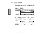
First Select Sequence.

 When concentrator X receives the command, it 

strips away the 02, substitutes 1F hex as the select address, and forwards 
the remaining command, 01<T>, to Concentrator 02, shown in figure 2-8. 

Figure 2-8  Concentrator to Concentrator Select Sequence

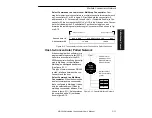
Second Select Sequence. 

Concentrator 02 then relays the command to 

Decoder 01 in a typical select sequence as shown earlier in figure 2-3 on 
page 2-4.
 It strips off the 01 from the command, substitutes 1D hex as the 
select address, and transmits the remaining data, <T>, to Decoder 01, shown 
in figure 2-9.

Figure 2-9  Concentrator to Decoder Select Sequence

RES  1F  REQ

1F ACK 

STX 01<T> ETX LRC

1F ACK

RES

Concentrator 02

Concentrator X

Start of Sequence

End of Sequence

R ES     1F     R EQ

1F AC K  

STX  01< T>  ETX  LR C

1F AC K

R E S

Concentrator 02

Concentrator X

Start of Sequence

End of Sequence

Summary of Contents for MS-5000

Page 1: ...MS 5000 Multidrop Concentrator User s Manual P N 83 005000 REV J...

Page 2: ...rantability of alleged product defects Products that are returned for warranty examination and that are found to be non warrantable are chargeable and are returned freight collect A copy of a purchase...

Page 3: ...p Communications Standard Single Concentrator Network 2 2 Multidrop Addresses 2 2 Data to the Host 2 2 Select Commands from the Host 2 4 Polling Cycle Timing 2 7 Multiple Concentrator Network 2 8 Mult...

Page 4: ...Figure 1 7 Multidrop LAN Wiring 1 7 Figure 1 8 DTE and DCE Host Connections 1 8 Figure 1 9 Host Connector on concentrator 1 8 Figure 1 10 Monitor Connector on concentrator 1 9 Figure 1 11 MS 5000 Bot...

Page 5: ...mmands 4 2 Table 4 2 Summary of MS 5000 Operational Commands 4 2 Table 4 3 Protocol Commands 4 7 Table 5 1 Profile Card Mode Descriptions for the MS 5000 5 2 Table 5 2 Calculating Binary Conversion 5...

Page 6: ...ions Chapter 3 provides instructions for configuring the MS 5000 concentrator by menu Chapter 4 provides instructions for configuring the MS 5000 concentrator by serial command Chapter 5 provides inst...

Page 7: ...S TED W ITH CLA SS A CO MP UTING DEVIC ES A ND HA S BE EN FO UND TO COMPLY WITH PART 15 O F FCC RULE S SEE INSTR UCTION MANUAL OP ERA TION IN A RE SID ENTIAL A REA MA Y CA USE UNACCE PTA BLE INTE RFER...

Page 8: ...viii MS 5000 Multidrop Concentrator User s Manual...

Page 9: ...tor 1 10 Step 4 Position Scanning Devices 1 11 Step 5 Install Concentrator 1 12 This chapter outlines the recommended steps for setting up your system and specific instructions for installing and atta...

Page 10: ...mated Scanning Devices The MS 5000 multidrop concentrator can be used with scanners or the combination of scan heads and decoders Call your Microscan representative for product specifications You may...

Page 11: ...d item flow J J J Drop Cable Object Detector Power supply MS 7000 Scanner Object RS 485 Detector Power supply Power supply MS 7000 Scanner Object Detector Power supply MS 7000 Scanner HOST Optional Mo...

Page 12: ...ar RJ 11 6 pin LAN cables to networked devices are pin to pin e Last device in network uses a 68 ohm terminal resistor see Appendix E Terminal Resistor on page A 9 f A new device can be added anywhere...

Page 13: ...rations on page A 7 Power 5 pin DIN LAN modular 6 pin RJ 11 Host 25 pin D subminiature Monitor 9 pin D subminiature HOST MONITOR LAN POWER Under ideal conditions maximum cable lengths can meet the dis...

Page 14: ...equired DC voltages a mating power connector is required Caution Switching power supplies for Microscan equipment with a switching noise of 75 mV or greater with 5 VDC or of 30 mV or greater with 12 V...

Page 15: ...ed correctly see Appendix E Terminal Resistor on page A 9 In the first multidrop trunk cable between the concentrator and the first logical device 1 transmit and reception lines are crossed see figure...

Page 16: ...5 pin D subminia ture socket The host is connected as a DTE data terminal equip ment device with 25 pin D subminiature connec tors Table 1 3 on page 1 9 shows pin assign ments Figure 1 9 Host Connecto...

Page 17: ...socket and cable Table 1 4 shows auxiliary terminal pin assignments Communication at this connector is RS 232 only Pin Signal Pin Signal 1 Chassis Ground 14 Transmit Data A 2 Transmit Data 15 Reserved...

Page 18: ...ured from a host or auxiliary terminal either by menu selection Chapter 3 serial command Chapter 4 Serial Commands or profile card command Chapter 5 Profile Card Configura tion Chapter 3 Menu Configur...

Page 19: ...User s Manual 1 11 1 Setup and Inst 4 Position Scanning Devices Position the scanning devices and decoders if used relative to the labels you will be scanning in your application Consult your scannin...

Page 20: ...he concentrator for the connectors and cables c Use the measurements provided in figure 1 11 to locate centers of mounting holes and drill four 5 32 inch 4 mm holes d Secure concentrator with four 6 3...

Page 21: ...the unit does not have housing use the measurements provided in figure 1 12 to locate the centers of the mounting holes Figure 1 12 MS 5000 without housing Mounting Diagram not full size 5 8 147 32 3...

Page 22: ...Chapter 1 Setup and Installation 1 14 MS 5000 Multidrop Concentrator User s Manual 1 Setup and Inst...

Page 23: ...equence 2 10 The MS 5000 concentrator s function is to control the flow of data between the host and two or more decoders or scanners printers etc Each device in the multidrop network is assigned an a...

Page 24: ...In a multidrop network each device is assigned a number from 01 to 50 However during poll and select sequences the concentrator provides back ground substitution from a table of hexadecimal ASCII valu...

Page 25: ...dinal re dundancy check character If the concentrator receives the data from the decoder and is able to validate it with an LRC calculation the concentrator responds with an ACK acknowl edgment If the...

Page 26: ...equests a trigger count command T from De coder 02 it will transmit the data string 02 T CR3 to the concentrator The concentrator takes this command strips off the 02 and substitutes the hex value 1F...

Page 27: ...et the carriage return as its own ETX character and terminate the command Select Reset Sequences Both the concentrator and the decoder can ter minate the select sequence by transmitting a RES reset to...

Page 28: ...that exceeds the Intercharacter Timeout Multiple Commands to More Than One Decoder Commands up the 127 characters total but no more than 64 characters to any single decoder can be concatenated to more...

Page 29: ...reater than the Turnaround Timeout setting which by default is 12 ms For a given baud rate it would seem that a simple multiplication of total characters times baud rate could be used to predict the d...

Page 30: ...naround Timeout for Concentrator 01 For example if Concentrator 01 is set to the default of 12 ms try setting Concentrator X to 25 ms you may need to experiment to determine the best setting For more...

Page 31: ...ator X Concentrator 02 responds by transmitting its hex poll character 1E an STX the decoder s multidrop address 01 then the decoder s data shown in figure 2 7 Figure 2 7 Concentrator to Concentrator...

Page 32: ...select address and forwards the remaining command 01 T to Concentrator 02 shown in figure 2 8 Figure 2 8 Concentrator to Concentrator Select Sequence Second Select Sequence Concentrator 02 then relay...

Page 33: ...s software or a programmable logic controller PLC can mimic a concentrator the MS 5000 concentrator itself can be config ured in Multidrop or User Defined Multidrop and assigned an address See figure...

Page 34: ...Chapter 2 Multidrop Communications 2 12 MS 5000 Multidrop Concentrator User s Manual 2 Multidrop Comm...

Page 35: ...ice Status Menu 3 15 Time Keeping Menu 3 15 Exiting and Saving Menu Changes 3 17 Note Menu configuration in a multidrop network as described in this chapter applies only to the MS 5000 concentrator Co...

Page 36: ...wn address D is the command to enter the Main menu CR carriage return terminates the command Note The carriage return is enabled as the default ETX character If ETX is undefined nulled then a time del...

Page 37: ...he following command line path To view Turnaround Timeout s new status in the menu press M to refresh the screen To return to the Main menu press M again To return to the Main menu at any time press E...

Page 38: ...MS 5000 Note Power must be available to the concentrator during the default proce dure Defining Special Characters To define any control character from the ASCII table Press SP once then enter the con...

Page 39: ...Rate is the first parameter for Host and LAN Port Aux Mode is the first parameter for Aux Port Communications Bold text represents default settings Baud Rate 9600 1200 19 2K 2400 38 4K 4800 600 Parity...

Page 40: ...h character to indicate the end of the character Data Bits Default Seven Options Seven Eight Number of bits in each character RS 422 Default RS 232 Options RS 232 RS 422 Used only in Point to Point pr...

Page 41: ...t is polling Intercharacter Timeout Default 15 ms Options 1 to 250 ms Intercharacter Timeout used only with Host Port is the concentrator s wait ing period between individual characters transmitted fr...

Page 42: ...m fifty to as few as one use the number of the last address you want polled For example if you know that the concentrator will have only six devices on the LAN you can speed up polling by setting Numb...

Page 43: ...modes unpolled and polled In unpolled mode all of the Point to Point protocols a concentrator transmits information without being asked for by the host In polled mode Multidrop Polling Mode D and Use...

Page 44: ...stop XOFF If an XOFF has been received from the host data will not be sent to the host until the host transmits an XON During the XOFF phase the host is free to carry on other chores and accept data...

Page 45: ...is nec essary when defining a new protocol to match a specific host protocol You may assign an address to a concentrator in User Defined protocol by entering any single ASCII character at the address...

Page 46: ...an address as any one character 01 hex to 7E hex in the ASCII table The address char acter chosen is used as the poll character and the subsequent ASCII char acter becomes the select character For exa...

Page 47: ...t CR M and LF J Options Up to five ASCII characters Allows you to send up to five ASCII characters to be added after the decoded message Note If User Defined Polling Mode D or Multidrop protocol is en...

Page 48: ...rds in a row before releasing the batch of five to the host See also C Send Partial Buffer to Host Command on page 4 13 for related informa tion Buffered data is transmitted to the host exactly as the...

Page 49: ...programs Hint Attach a tag to each device to identify its multidrop address Time Keeping Menu Allows you to determine the way that time and date information is prepended added to the beginning to dec...

Page 50: ...l was decoded is prepended to the label data Hours Options 0 to 23 Allows you to set the current time in hours Minutes Options 0 to 59 Allows you to set the current time in minutes Seconds Options 0 t...

Page 51: ...es date and time date output from the address of the device and the label data Exiting and Saving Menu Changes To exit the menu and save menu changes for power up press ESC escape key The following co...

Page 52: ...Chapter 3 Menu Configuration 3 18 MS 5000 Multidrop Concentrator User s Manual 3 Serial Config...

Page 53: ...onfiguration and operational utility com mands All of the MS 5000 s menu configuration changes can also be made by com mand strings from the host Serial commands listed in this chapter apply ONLY to t...

Page 54: ...Postamble 51 Kfdata CR Host Protocol 51 Kgdata CR Blocking Factor 51 Khdata CR Host Port Turnaround Timeout 51 Kidata CR Host Port Intercharacter Timeout 51 Kjdata CR RTS CTS 51 Kkdata CR XON XOFF 51...

Page 55: ...haracter When using serial configuration commands note the following conventions Parameters and data fields are case sensitive that is characters must be entered as upper or lower case as specified Al...

Page 56: ...xample To change the timeout to 30 ms enter 51 Kh30 CR Intercharacter Timeout Time the concentrator will wait between inidvidual characters from the host Format 51 Kitimeout CR Example To change the t...

Page 57: ...RS 422 Format 51 Kmstatus CR Example To enable RS 422 enter 51 Km1 CR Turnaround Timeout Number of Devices Time the concentrator will wait between inidvidual characters from a LAN device Format 51 Knt...

Page 58: ...ost If this occurs default the concentrator see Appendix C Defaulting the MS 5000 on page A 6 If selecting one of the options from 0 to 4 Point to Point Point to Point with RTS CTS Point to Point with...

Page 59: ...s can be assigned any ASCII character except a null Control characters are used to define RES through NAK except Address Table 4 3 lists the control characters used for these data fields Refer to Tabl...

Page 60: ...ands The seven commas keep the current values for EOR XON XOFF RES REQ STX and ETX F and U assign an ACK and a NAK respec tively to the To Host ACK and NAK commands The remaining four To Host protocol...

Page 61: ...ond data field CR Example To enable Postamble and send an FF form feed character enter 51 Ke1 L CR LRC The exclusive OR of all characters following SOM start of message up to and including the EOM end...

Page 62: ...Blocking Factor to 5 enter 51 Kg5 CR Full Screens Toggle between full menu view and command line only view Format 51 Kqstatus CR Example To enable Full Screens enter 51 Kq1 CR Battery backed RAM2 Sav...

Page 63: ...e and Date Output Set format for time and date output KJtime output date output time separator Hour 0 to 23 Minute 0 to 59 Second 0 to 59 DOW day of week Sun 1 Wed 4 Sat 7 Mon 2 Thu 5 Tue 3 Fri 6 Mont...

Page 64: ...s To save changes made by host command to the concentrator for power up enter 51 Z CR Example Saving Decoder Changes To save changes made by host com mand to a decoder for power up enter the decoder s...

Page 65: ...will release a batch of 2 records to the host See Blocking Factor on page 4 10 Uploading Current Time Uploads the current date and time to the host with the 51 address prepended Format 51 CR Uploading...

Page 66: ...Chapter 4 Serial Commands 4 14 MS 5000 Multidrop Concentrator User s Manual 4 Operations...

Page 67: ...Most of the menu configuration changes to the MS 5000 concentrator can also be made with the profile card The profile card available from Microscan as an accessory 97 100001 XX is not essential to the...

Page 68: ...y for the host port Stop Bits Defines Stop Bits for the host port Data Bits Defines Data Bits for the host port 4 Preamble Enables disables Preamble Postamble Enables disables Postamble 5 Protocol Def...

Page 69: ...ALL of the data switch settings are correct for the selected mode before pressing the load button 3 Press the LOAD button 4 A beeper will sound This initializes the change and saves it to non vol ati...

Page 70: ...Write Read Default Menu Mode 1 Copy Configuration and Assign Address Data Switchesa a Also used for mode 2 9 10 11 and 12 Address Address Address Address 1 2 3 4 5 6 1 2 3 4 5 6 1 2 3 4 5 6 1 2 3 4 5...

Page 71: ...settings Mode 3 Host Port Communications Data Switches Baud Rate Parity Stop Bits Data Bits 1 2 3 4 5 6 7 600 None One Seven 1200 Even Two Eight 2400 Odd 4800 9600 19200 38400 Mode 4 Preamble Postambl...

Page 72: ...Protocol Host Port RS 422 Data Switches Protocol RS 422 1 2 3 4 Point to Point Disable Point to Point with RTS CTS Enable Point to Point with XON XOFF Point to Point with RTS XON Polling Mode D Multid...

Page 73: ...ud Rate Parity Stop Bits Data Bits 1 2 3 4 5 6 7 2400 None One Seven 4800 Even Two Eight 9600 Odd 19 2K 38 4K Mode 8 LAN Port Communications Data Switches Baud Rate Parity Stop Bits Data Bits RS 422 1...

Page 74: ...n binary format See mode 1 switch settings for timeout ranges from 0 1 seconds to 5 sec onds Although not shown for mode 1 switches 7 and 8 are OFF for 1 through 50 See Binary Calculations on page 5 9...

Page 75: ...the profile card represent the eight data bits that define any number from 0 to 255 in binary format To convert a number to its binary equivalent 1 Determine which decimal equivalent 1 2 4 8 16 32 64...

Page 76: ...t does not exceed the remainder number 5 Put a one 1 above that number 6 Continue this process until the remainder equals zero 0 as follows 250 128 122 64 58 32 26 16 10 8 2 2 0 OFF positions on the d...

Page 77: ...nts Appendix A MS 5000 Specifications A 2 Appendix B Quick Reference Tables A 3 Appendix C Defaulting the MS 5000 A 6 Appendix D Ground and Shield Considerations A 7 Appendix E Terminal Resistor A 9 A...

Page 78: ...Bits 1 or 2 Baud Rates 600 1200 2400 4800 9600 19 2K 38 4K I O Port 6 pin 6 wire modular Protocols Multidrop User Defined Multidrop up to 50 devices per concentrator Auxiliary Monitor Port Communicat...

Page 79: ...10 0A LF J 42 2A 74 4A J 106 6A j 11 0B VT K 43 2B 75 4B K 107 6B k 12 0C FF L 44 2C 76 4C L 108 6C l 13 0D CR M 45 2D 77 4D M 109 6D m 14 0E SO N 46 2E 78 4E N 110 6E n 15 0F SI O 47 2F 79 4F O 111...

Page 80: ...king Factor 51 Khdata CR Host Port Turnaround Timeout 51 Kidata CR Host Port Intercharacter Timeout 51 Kjdata CR RTS CTS 51 Kkdata CR XON XOFF 51 Kldata CR LAN Port Baud Parity Stop Bits and Data Bits...

Page 81: ...R 52 S 53 04 22 23 29 T 54 U 55 05 24 25 30 V 56 W 57 06 26 27 31 X 58 Y 59 07 28 29 32 Z 5A 5B 08 2A 2B 33 5C 5D 09 2C 2D 34 5E _ 5F 10 2E 2F 35 60 a 61 11 0 30 1 31 36 b 62 c 63 12 2 32 3 33 37 d 6...

Page 82: ...te Read Default Menu on page 5 4 Listen for two beeps in suc cession the second louder than the first If the beeps do not occur as described repeat the default procedure Shorting Pins 7 and 11 If a pr...

Page 83: ...nterference is twisted and or shielded or encased in grounded conduit and the conduit or shielding drain line is grounded only to earth ground at the host as shown in figure A 4 1 Examine the shieldin...

Page 84: ...000 Multidrop Concentrator User s Manual Appendices Figure A 4 Network Grounding Diagram H ost C oncentrator D ecoder D ecoder C oncentrator D ecoder D ecoder S hielding C om m unications Cable Earth...

Page 85: ...in last MS 2000 MS 3000 With Other Devices Terminal resistors can be installed externally by wir ing the resistor into the last T junction box or by wiring within the connector of the last scanner or...

Page 86: ...d a ground loop potential and the possibility of noise interfer ence exists Therefore cable lengths are limited to a maximum of 50 feet 15 24 m Despite being the most limited this interface is used fr...

Page 87: ...st to the devices Configuration The method used to change factory default settings for operational features to match a specific application Configuration can be done through menu selection or with ser...

Page 88: ...r odd Point to Point A protocol consisting of a single communications event typically used to connect a bar code reader to a CRT terminal or a host computer Polled Protocol A communication protocol in...

Page 89: ...specific command datum a greater than symbol and a CR carriage return Serial Configuration The method of changing factory default settings via command strings The structure for a multidrop system cons...

Page 90: ...A 14 MS 5000 Multidrop Concentrator User s Manual Appendices...

Page 91: ...rofile card 5 8 by serial command 4 10 C Cabling maximum distances 1 5 Communications from the host 2 4 2 6 to the host 2 2 2 4 Communications menu 3 5 3 8 Configuration commands 4 3 4 11 Configure Co...

Page 92: ...program 3 2 exiting program 3 17 Menu Configuration Program exiting 3 4 loss of communications 3 4 saving menu changes 3 4 Menu Configuration entering by profile card 5 4 Monitor Connector 1 9 Mountin...

Page 93: ...menu selection 3 13 by profile card 5 5 by serial command 4 9 Power Connector 1 6 Preamble by menu selection 3 13 by profile card 5 5 by serial command 4 9 Profile Card binary calculation 5 9 default...

Page 94: ...am 1 3 T terminal communications 1 10 Terminal Resistor A 9 terminal resistor 1 4 Time Keeping commands by serial commands 4 11 Time Keeping menu 3 15 3 17 Time Output 3 16 Time Stamp Separator 3 17 T...

Reviews: