Chapter
2
System Components
2-10
Vision MINI Smart Camera Guide
Status Indicators
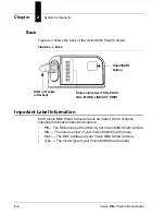
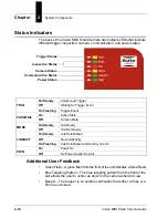
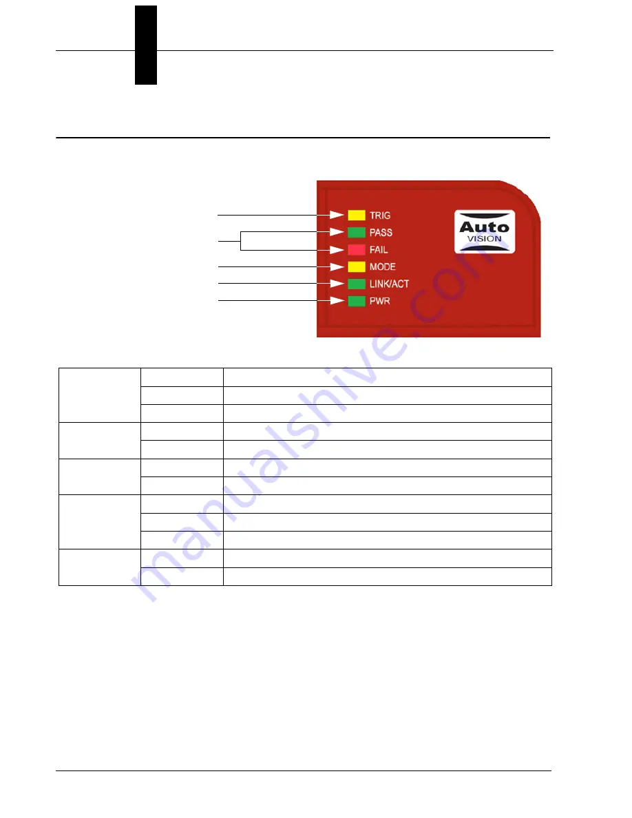
The back of the Vision MINI Smart Camera has multiple LEDs that indicate
different trigger, inspection, camera, communication, and power states.
Additional User Feedback
•
Green Flash – A green flash from the front of the unit indicates a Good Read.
•
Blue Targeting Pattern – The blue targeting pattern from the front of the
unit allows the user to center an object in the camera’s field of view.
•
Beeper – The beeper is an audible verification that either a Pass or a
Fail has occurred.
TRIG
On Steady
Continuous Trigger
Off
Waiting for Trigger Event
On Flashing
Trigger Event
PASS/FAIL
On
Active State
Off
Inactive State
MODE
On Steady
Unit Ready
Off
Unit Not Ready
LINK/ACT
On Steady
Link Established
Off
No Link/Activity
On Flashing
Link Established and Activity on Link
PWR
On
Power On
Off
No Power Applied to Unit
Trigger Status
Inspection Status
Camera Status
Communication Status
Power Status
Summary of Contents for Vision MINI Smart Camera
Page 1: ...Vision MINI Smart Camera Guide 84 016300 02 Rev J ...
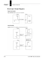
Page 16: ...Chapter 2 System Components 2 6 Vision MINI Smart Camera Guide Direct Input Output Diagrams ...
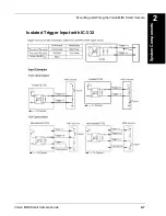
Page 18: ...Chapter 2 System Components 2 8 Vision MINI Smart Camera Guide New Master Input with IC 332 ...
Page 24: ...Chapter 2 System Components 2 14 Vision MINI Smart Camera Guide ...
Page 32: ...Appendix A Connector Pinouts A 4 Vision MINI Smart Camera Guide ...
Page 42: ...Appendix B Cable Specifications B 10 Vision MINI Smart Camera Guide ...
Page 62: ...Appendix E Vision MINI Diagnostic Boot Mode E 4 Vision MINI Smart Camera Guide ...
Page 66: ...Appendix F USB Power Management F 4 Vision MINI Smart Camera Guide ...

