Operation of Board Components
2 2
R e v i s i o n 3
Push-Button Switches
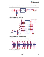
Four active low push-button switches are provided on the board for user debug. You can remove the
corresponding jumpers from the 4 x 2 Header to detach any of the four push-button switches from the
FPGA I/O. Schematics are shown in
and
.
Figure 3-5 • Push-Button Switches Schematic
Figure 3-6 • Jumper Header Schematic for Push-Button Switches
pb_sw1
pb_sw2
pb_sw3
pb_sw4
VCC_3_3
1
4
2
3
SW2
SW PUSHBUTTON-SPST-2
SW2
SW PUSHBUTTON-SPST-2
1
4
2
3
SW3
SW PUSHBUTTON-SPST-2
SW3
SW PUSHBUTTON-SPST-2
1
4
2
3
SW4
SW PUSHBUTTON-SPST-2
SW4
SW PUSHBUTTON-SPST-2
1
2
3
4
5
6
7
8
RP2
10K-0603x4 RPack
RP2
10K-0603x4 RPack
1
4
2
3
SW1
SW PUSHBUTTON-SPST-2
SW1
SW PUSHBUTTON-SPST-2
pb_sw1
pb_sw3
pb_sw4
pb_sw2
agl_b3_p23 [4,8]
agl_b3_p22 [4,8]
agl_b3_p21 [4,8]
agl_b3_p20 [4,8]
1
2
3
4
5
6
7
8
JP15
4x2 Header for Jumper
JP15
4x2 Header for Jumper
Summary of Contents for IGLOO nano Starter Kit
Page 1: ...IGLOO nano Starter Kit User s Guide ...
Page 6: ......
Page 9: ...IGLOO nano Starter Kit Revision 3 9 Figure 1 3 Bottom Silkscreen ...
Page 14: ......
Page 28: ......
Page 30: ......
Page 32: ......
Page 34: ......
Page 36: ......
Page 41: ......


