background image

Gigabit Ethernet Switch – Quick Installation Guide 

       Page 6 of 9 

_______________________________________________________________________________________________ 

©2017_MICROSENS GmbH & Co. KG_Küferstr. 16_59067 Hamm/Germany_www.microsens.com 

2.5


Installing SFP Modules 

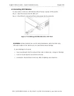
You can install or remove a SFP module without having to power off the switch. 

Step 1: 

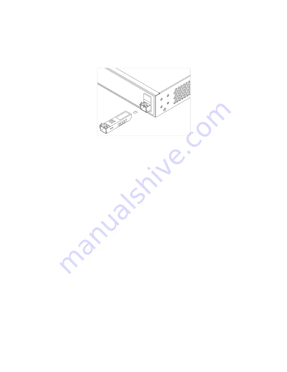
Insert the module into the SFP port. 

Step 2: 

Press firmly to ensure that the module seats into the connector. 


Figure 7: Installing a SFP Module into a SFP Port 


WARNING: Infrared radiation as used for data transmission within the fiber optic, 
although invisible to the human eye, can nevertheless cause damage. 


To avoid damage to the eyes: 


never look straight into the output of fiber optic components – danger of blinding! 


cover all unused optical connections with caps. 


commission the transmission link only after completing all connections. 


Summary of Contents for MS453514M

Page 1: ... 2017_MICROSENS GmbH Co KG_Küferstr 16_59067 Hamm Germany_www microsens com Gigabit Ethernet Switch Quick Installation Guide MS400834M Version 1 0 ...

Page 2: ...on 1 1 1 Overview 1 1 2 Front View of the Switch 1 1 3 Rear View of the Switch 1 1 4 LED Descriptions 1 1 5 Mode Reset Button 3 2 Installing the Switch 4 2 1 Package Contents 4 2 2 Mounting the in a 19 inch Rack 4 2 3 Mounting the Switch on Desk or Shelf 5 2 4 Connecting the AC Power Cord 5 2 5 Installing SFP Modules 6 3 Initial Configuration of Switch 7 3 1 Initial Switch Configuration Using Web ...

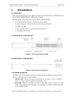
Page 3: ...to restore the switch to factory defaults To install the switch To use a Web browser to initially configure the switch To troubleshoot the switch 1 2 Front View of the Switch Figure 1 Front panel of the switch 1 3 Rear View of the Switch Figure 2 Rear panel of the switch 1 4 LED Descriptions The LEDs on the front panel provide users with switch status checking and monitoring There are three types ...

Page 4: ...us by reading the LED behaviors per the table below When Link Act Speed Mode LED Lit LED Color State Description RJ45 Ports Green On The port is enabled and established a link to connected device and the connection speed is 1000Mbps Green Blinking The port is transmitting receiving packets and the connection speed is 1000Mbps Amber On The port is enabled and established a link to connected device ...

Page 5: ...ow users can easily judge which task is being per formed by reading the LED behaviors while pressing the mode reset button Once the LED behaviors are correctly displayed users may just release the button Table 4 Mode Reset Button Descriptions When PoE Mode LED Lit LED Color State Description RJ45 Ports Green On The port is enabled and supplying power to connected device Amber On An abnormal state ...

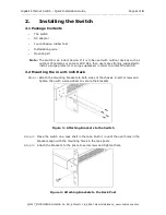
Page 6: ...ch as outdoor IP cameras or outdoor WiFi APs then users are strongly suggested to install a surge protector or surge suppressor in order to protect the switch 2 2 Mounting the in a 19 inch Rack Step 1 Attach the mounting brackets to both sides of the chassis Insert screws and tighten then with a screwdriver to secure the brackets Figure 3 Attaching Brackets to the Switch Step 2 Place the switch on...

Page 7: ...sk or Shelf Step 1 Verify that the workbench is sturdy and reliably grounded Step 2 Attach the four adhesive rubber feet to the bottom of the switch Figure 5 Attaching the Rubber Feet 2 4 Connecting the AC Power Cord Step 1 Connect the AC power cord to the AC power receptacle of switch Step 2 Connect the other end of the AC power cord to the AC power outlet Step 3 Check the SYS LED If it is ON the...

Page 8: ...h Step 1 Insert the module into the SFP port Step 2 Press firmly to ensure that the module seats into the connector Figure 7 Installing a SFP Module into a SFP Port WARNING Infrared radiation as used for data transmission within the fiber optic although invisible to the human eye can nevertheless cause damage To avoid damage to the eyes never look straight into the output of fiber optic components...

Page 9: ...s as follows 1 Power up the PC that you will use for the initial configuration Please make sure the PC has the Ethernet RJ45 connector to be connected to the switch via standard Ethernet LAN cable 2 Reconfigure the PC s IP address and subnet mask as below so that it can communicate with the switch The method to change the PC s IP address for example for a PC running Windows 7 8 x 10 is as follows ...

Page 10: ...check the port LED on the switch to make sure the link status of the PC s is OK 5 Run your Web browser on the PC enter the factory default IP address to access the switch s Web interface If your PC is configured correctly you will see the login page of the switch as shown by Figure 9 below Figure 8 Web Interface login page If you do not see the above login page please perform the following steps R...

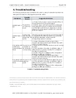
Page 11: ...oth the switch and the connected device 2 Make sure the connected device is up and running correctly 3 If the symptom still exists try different cable or different port in order to identify if it is related to the cable or specific port 4 Check if the port is disabled in the configuration settings via WEB user interface Port Status LED is Off in the PoE Mode The port is not supplying power 1 Check...

Reviews: