System Core 5
miriac EK-5744 User Manual
V 1.2
26/53
© MicroSys Electronics GmbH 2017
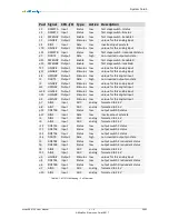
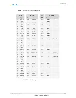
Pad Signal CPU-I/O Type
Active Description
c1
DPWSTA Input
Status
low
first stage switch-I status
c2
DPWSTC Input
Status
low
first stage switch-II status
c6
PWENC# Output
Enable
low
first stage switch-II enable C
c7
HAIN4#
Output
Stimulus low
unique for this analog input
c9
DIN1
Input
Data
low
inverted input pin state
c10
HAIN3#
Output
Stimulus low
unique for this analog input
c11
DPWSTB Input
Status
low
first stage switch-I redundant status
d7
DOUT2
Output
Data
high
non-inverted output pin state
d11 PWEND# Output
Enable
low
first stage switch-II enable D
e15
PWENB# Output
Enable
low
first stage switch-I enable B
f17
HAIN5#
Output
Stimulus low
unique for this analog input
g17
HAIN6#
Output
Stimulus low
unique for this analog input
k4
HDIN0#
Output
Stimulus low
unique for this digital input
l1
DOUT1
Output
Data
high
non-inverted output pin state
l3
HAIN2#
Output
Stimulus low
unique for this analog input
m3
HDIN2#
Output
Stimulus low
unique for this digital input
m15 HAIN1#
Output
Stimulus low
unique for this analog input
n15 HDIN3#
Output
Stimulus low
unique for this digital input
p5
HDIN1#
Output
Stimulus low
unique for this digital input
p7
AIN5
Input
ADC
analog
formated to 3.3V
p8
AIN7
Input
ADC
analog
formated to 3.3V
p11 DOSTA0 Input
Status
low
output switch 0 status
p17 DIN3
Input
Data
low
inverted input pin state
r5
AIN1
Input
ADC
analog
formated to 3.3V
r6
AIN3
Input
ADC
analog
formated to 3.3V
r10
DOSTA1 Input
Status
low
output switch 1 status
r11
DOSTA2 Input
Status
low
output switch 2 status
r12
DOSTA3 Input
Status
low
output switch 3 status
r16
DOUT0
Output
Data
high
non-inverted output pin state
t5
DOSTB2 Input
Status
low
output switch 2 redundant status
t6
DOSTB3 Input
Status
low
output switch 3 redundant status
t8
AIN4
Input
ADC
analog
formated to 3.3V
t11
AIN6
Input
ADC
analog
formated to 3.3V
u3
HAIN0#
Output
Stimulus low
unique for this analog input
u4
DOSTB1 Input
Status
low
output switch 1 redundant status
u6
DOSTB0 Input
Status
low
output switch 0 redundant status
u7
AIN0
Input
ADC
analog
formated to 3.3V
u10 AIN2
Input
ADC
analog
formated to 3.3V
Table 5-1: MCU Pin Mapping – Full Overview


