miriac SBC-S32G-R3_User Manual
V 3.2
41/65
© MicroSys Electronics GmbH 2021
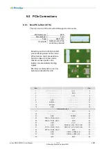
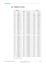
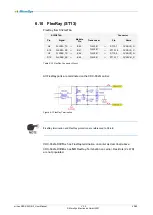
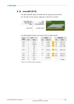
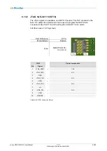
Pin:
Pin:
41
+3.3V
LED-WWAN#
➔
nc
42
43
GND
LED_WLAN#
➔
nc
44
45
Reserved
➔
nc
LED_WPAN#
➔
nc
46
47
Reserved
➔
nc
+1.5V
48
49
Reserved
➔
nc
GND
50
51
Reserved
➔
nc
+3.3V
52
Table 6-26 mPCIe Slot Pinout
The following table shows the internal connections:
ST15
MXM1
S32G274A
Pin
Name
Pin
Signal
Pin
Name
23
PCIE0_RX0_N
→
T75
→
AC19
PCIE0_RX0_N
25
PCIE0_RX0_P
→
T76
→
AB19
PCIE0_RX0_P
31
PCIE0_TX0_N
←
T90
←
Y16
PCIE0_TX0_N
33
PCIE0_TX0_P
←
T91
←
W16
PCIE0_TX0_P
Table 6-27 mPCIe Slot SerDes_0_Ln0 Assignment
AC coupling capacitors for PER0_N and PER0_P have to be placed on
the plug-in card near the transmitter.
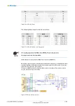
USB channel is connected to USB2 from hub J33 (USB2514).
Mini-PCIe card connector is interfaced to SIM-card connector on CRX-S32G carrier
via UIM-interface. SIM-card is located on bottom under mini-PCIe card. It is acces-
sible from the right side of the board.
If there is a SIM-card on the module either card on module or the card on carrier
may be used, but only one at time.
Figure 6-3 SIM-card interface on carrier


