System Core, Boot Configuration 5
miriac SBC-S32V User Manual
V 1.1
39/81
© MicroSys Electronics GmbH 2017
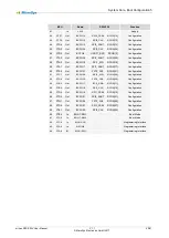
5.5.1 MCU Pinout
MCU
Board
S32V234
Function
Pin
Port
Dir
Signal
Signal
RCON
1
PTD1
Out
BCFG23
SPI2_CS0#
RCON[23]
Configuration
2
PTD0
Out
BCFG29
FXT0_CH1
RCON[29]
Configuration
3
PTH7
Out
BCFG22
SPI2_SIN
RCON[22]
Configuration
4
PTH6
Out
BCFG6
UART1_TXD
RCON[6]
Configuration
5
PTE7
Out
RSTOUT#
Modul Rest Output
6
PTH2
n.c.
not connected
7
In
+3V3
Supply
8
In
VREFH
+3.0V
9
In
VREFL
Reference Ground
10
GND
Reference Ground
11
PTB7
Out
FRSTI#
eMMC Reset
12
PTB6
Out
PWEN
PSU enable
13
GND
Reference Ground
14
PTH1
In
QSPI-SEL
GPIO[158]
FLASH/SDHC Mux
15
PTH0
IO
TRTC#
Time Stamp RTC
16
PTE6
In
IRTC#
Interrupt RTC
17
PTE5
Out
PORST#
EXT_POR#
PowerOnReset
18
PTB5
Out
RESET#
RESET#
Reset
19
PTB4
In
FCCU-F0
FCCU_F0
Failure Check&Correction
20
PTC3
In
LD4
yellow Led
21
PTC2
In
+3V3
ADC Divider 3:4
22
PTD7
Out
NMI
NMI
Interrupt
23
PTD6
Out
FCCU-F1
FCCU_F1
Failure Check&Correction
24
PTD5
OUT
BCFGE#
Configuration Enable
25
PTC1
In
+3.3V
ADC Divider 3:4
26
PTC0
In
+1.8V
ADC direct
27
PTF7
In
+1.35V
ADC direct
28
PTF6
In
+1.0V
ADC direct
29
PTF5
In
+VIN
ADC Divider 1:11
30
PTF4
Out
BCFG2
FLXR_RXD
RCON[2]
Configuration
31
PTB3
Out
BCFG0
FLXR_TENB
RCON[0]
Configuration
32
PTB2
Out
BCFG1
FLXR_TXD
RCON[1]
Configuration
33
PTB1
Out
BCFG3
UART0_RXD
RCON[3]
Configuration
34
PTB0
Out
BCFG4
UART0_TXD
RCON[4]
Configuration
35
PTF3
Out
BCFG7
I2C0_SDA
RCON[7]
Configuration
36
PTF2
Out
BCFG8
I2C0_SCL
RCON[8]
Configuration
37
PTA7
Out
BCFG9
I2C1_SDA
RCON[9]
Configuration
38
PTA6
Out
BCFG10
I2C1_SCL
RCON[10]
Configuration
39
PTE4
Out
BCFG14
SPI0_SIN
RCON[14]
Configuration
40
GND
Reference Ground

