System Core, Boot Configuration 5
miriac SBC-S32V User Manual
V 1.1
34/81
© MicroSys Electronics GmbH 2017
5.2
Boot Mode Configuration
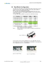
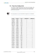
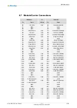
The SBC-S32V board offers several different boot modes to choose from. The set-
tings can be done via the sliding switch BMD on the module and the dipswitch
BOOT on the carrier according to following table.
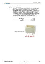
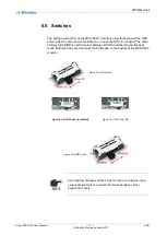
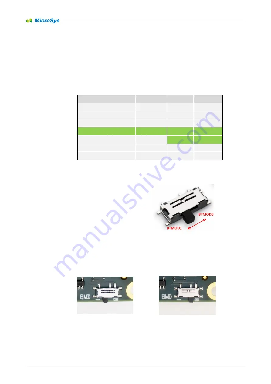
The switch BMD sets the BMODE[0] and BMODE[1] signals of the CPU to low,
while the two configuration resistors BMD0 and BMD1 are used to set a fixed low
value on these lines.
The parts BMD, BMD0 and BMD1 are located on the MPX-S32V module.
green denotes the default configuration
Note 1)
BMD0 and BMD1 are soldered resistors (size 0402) and not intended to be
changed by user.
Shown positions set the according BTMOD0/1 line to low. BTMOD0 controls the
CPU configuration port PC9, i.e. BOOTMOD(0), while BTMOD1 is connected to the
CPU configuration port PC10, i.e. BOOTMOD(1).
Boot Mode
BMD-Switch
BMD0
1)
BMD1
1)
Serial Download, virgin device
No function
installed
installed
Serial Download, virgin device
Position 0
removed
installed
Serial Download, prog. device
Position 1
removed
installed
RCON Boot, if no fuses
Position 0
installed
removed
Serial Download, prog. device
Position 1
installed
removed
RCON Boot, no fuses
Position 0
removed
removed
Serial Download, prog. device
Position 1
removed
removed
Figure 16: BMD Switch
Figure 18: Position BTM1=low
Figure 17: Position BTM0=low

