Switches, Buttons and Jumpers 7
miriac SBC-T1024 User Manual
V 2.3
60/70
© MicroSys Electronics GmbH 2017
7
Switches, Buttons and Jumpers
7.1
Boot Device Switch
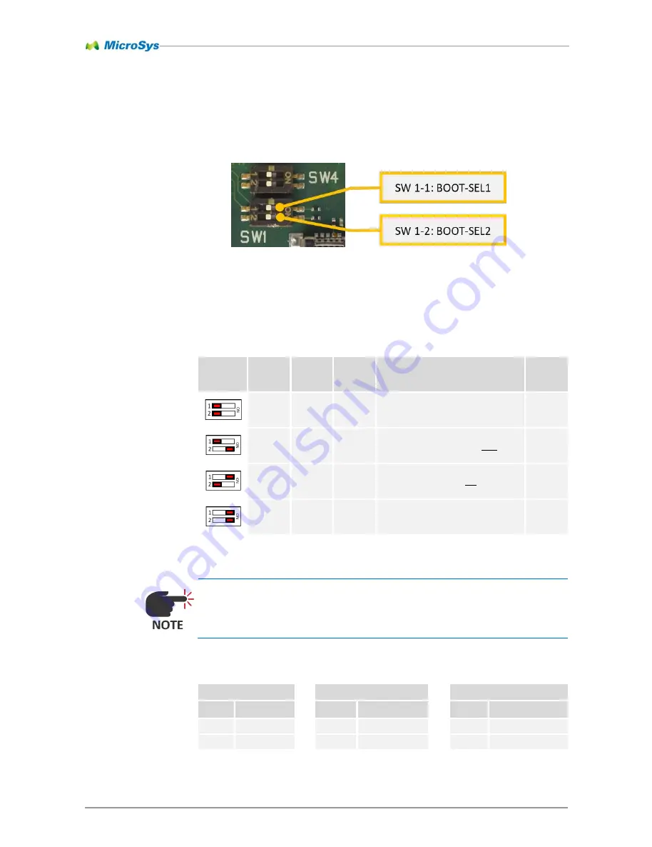
The boot device can be selected by the switch “SW1”.
The boot device switches implement a maximum of four possible boot devices. The
following boot devices are supported by the T1024:
SW1 inverts the logic levels of the BOOT-SELx pins. By setting the switch to ON the
corresponding pin is actually pulled low (grounded).
The following table shows the internal connections of the BOOT-SEL pins:
SW1
ST4
Microcontroller
Switch
Signal
Pin
Signal
Pin
Name
1-1
BOOT-SEL1
→
T134
BOOT-SEL1
→
19
PTA17
1-2
BOOT-SEL2
→
T133
BOOT-SEL2
→
20
PTA18
Table 7-2 BOOT-SELx pin assignment
Setting
SW 1-1
SW 1-2
Boot
device
Features
Boot
location
OFF
OFF
SPI
Flash
NAND flash is connected to CS1#
module
OFF
ON
NAND
Flash
NAND flash is connected to CS0#
module
ON
OFF
microSD
Card
-
NAND flash is connected to CS1#
-
SPI Flash on module is not accessible
SD/MMC interface: 8 bit
-
carrier
board
ON
ON
microSD
Card
-
NAND flash is connected to CS1#
-
SPI Flash on module is accessible
SD/MMC interface: 4 bit
-
carrier
board
Table 7-1 Boot device settings
Figure 7-1 Boot Device Switch
All manuals and user guides at all-guides.com


