background image

4     ArtixScan 1800f Installation and Operation Manual

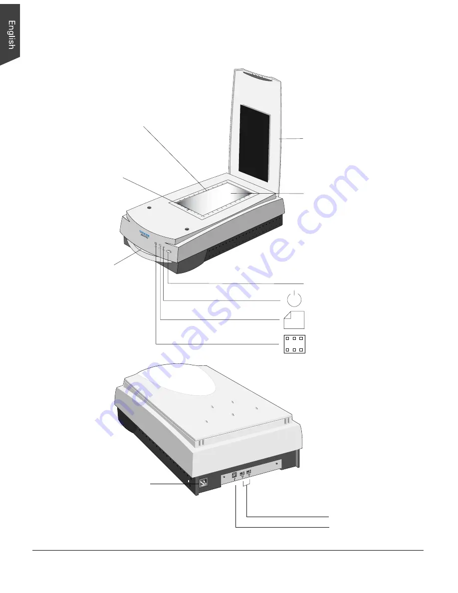
Horizontal ruler

Scanner lid

Glass surface
(Upper scan bed)

Vertical ruler

Taking a closer look

Transparency tray
(Lower scan bed)

Power button

Power indicator (green)

Transparency Ready indicator
(amber)

Reflective Ready indicator
(amber)

FireWire ports (2)

USB 2.0 port (1)

Power connector

Summary of Contents for ArtixScan 1800f

Page 1: ...Microtek ArtixScan 1800f Installation and Operation Manual...

Page 2: ...s of the copyright holder Microtek bears no responsi bility for the unauthorized use of copyrighted materials To obtain optimal results from the Microtek scanning software and user s manual you should...

Page 3: ...PositioningTransparent Film 12 Using the Glass Holder 13 Using the Other Film Holders 14 A Using the 35mm Slide Holder 15 B Using the 35mm Filmstrip Holder 15 C Using the 6 x 9 cm Film Holder 17 D Usi...

Page 4: ...iv...

Page 5: ...ou in the installation and operation of your scanner and the information provided covers both Macintosh and PC environments System Requirements CD ROM drive for installing software Color display with...

Page 6: ...ke sure that the scanning surface will not be exposed to direct sunlight or other sources of bright light Avoid placing the scanner close to sources of extreme cold or heat Avoid connecting the scanne...

Page 7: ...ct Microtek s customer service department 1 ArtixScan 1800f scanner 2 1 FireWire card 2 2 FireWire cable 2 3 USB 2 0 cable backward compatibility to USB 1 1 2 4 Power cord 2 5 Microtek CD ROM ScanWiza...

Page 8: ...ler Scanner lid Glass surface Upper scan bed Vertical ruler Taking a closer look Transparency tray Lower scan bed Power button Power indicator green Transparency Ready indicator amber Reflective Ready...

Page 9: ...ing slightly from the bottom of the scanner Shipping the Scanner If you have to transport the scanner the scanner must be locked To lock the scanner follow the steps below 1 Turn off the scanner if yo...

Page 10: ...install ScanWizard Pro the installer program will install the Color Matching System driver program and ask you to perform Color Matching for your monitor and printer The Color Matching System feature...

Page 11: ...pped with a built in FireWire port This port should be designated with the FireWire symbol shown to the left For PC users the FireWire card should be installed and should work properly in your compute...

Page 12: ...and connect the other end of the cable to the scanner s FireWire port 3 Press the power button on the front panel and wait for the lights to stop blinking and stay on steady The scanner will be detect...

Page 13: ...B 2 0 add on card that works properly in your computer For more details on how to install the Hi Speed USB 2 0 add on card in your computer please refer to the documentation that came with your purcha...

Page 14: ...users with a Hi Speed USB 2 0 card installed For PC users with a built in USB port 3 Press the power button on the front panel and wait for the lights to stop blinking and stay on steady The scanner...

Page 15: ...ou use the upper scan bed of the ArtixScan 1800f The upper scan bed is used for scanning reflective materials such as photos and prints 1 Open the scanner lid Note To scan a book or thick materials do...

Page 16: ...is used to scan non standard sized transparent film Caution Make sure that the calibration slit faces the front of the scanner when you insert the holder into the transparency bay the drawer of lower...

Page 17: ...holder 2 Place the vinyl strip on the edges of the transparency to secure the film in place 3 Insert the holder all the way into the transparency bay the drawer or lower compartment of the scanner Ca...

Page 18: ...cular type of standard sized film For instance use the 4 x 5 film holder to scan 4 x 5 film or use the 35mm filmstrip holder to scan 35mm filmstrips 1 1 1 2 1 1 1 2 2 2 2 1 1 1 2 1 2 2 2 3 2 4 2 5 2 6...

Page 19: ...lace the slide holder in the Main Holder 3 Insert the whole assembly into the transparency bay the drawer or lower compartment of the scanner B Using the 35mm Filmstrip Holder Two strips of six frames...

Page 20: ...p s frame by frame partitions 2 Put the filmstrip holder into the Main Holder 3 Insert the whole assembly into the transparency bay the drawer or lower compartment of the scanner Frame by frame partit...

Page 21: ...everal different film sizes of transparencies including 6 x 4 5 cm 6 x 6 cm 6 x 7 cm and 6 x 9 cm 1 Place the film into the holder a Push on the side to open the lid b Place the film in the holder c P...

Page 22: ...pieces of 4 x 5 film at a time 1 Place the film into the holder a Push on the side to open the lid b Place the film in the holder c Pull down the side to close the lid 2 Put the film holder into the...

Page 23: ...the Start menu in Windows The first time you launch ScanWizard Pro you will be asked to perform Color Matching for your monitor and printer 2 Once ScanWizard Pro is launched go to the Preview window...

Page 24: ...ginal bring up the Settings Window and select None on the Descreen options menu To scan printed material on the Descreen options menu select the suitable descreen level Newspaper Art Magazine etc 7 If...

Page 25: ...ion are included in the scanner accessories package The calibration target is very delicate and must be handled carefully as follows Gently remove the target from its protective sleeve and avoid touch...

Page 26: ...target position so that it is horizontally in the center of the glass surface B Positioning the Transparent Target 1 Place the target face down in the 4 x 5 Film Holder Note that the side of the targ...

Page 27: ...en instructions to generate your ICC profile Choose the proper target media select Reflective for reflective material otherwise select Positive Select the date code and target type to match your targe...

Page 28: ...h ScanWizard Pro 2 From the Preview window click the Scan Material icon Select the Reflective icon for reflective materials select the Positive Transparency icon Positive Film for transparencies and s...

Page 29: ...ion Optical 1800 dpi x 3600 dpi Interpolated 14400 dpi x 14400 dpi Dimensions L x W x H 24 7 x14 8 x5 1 627 38x375 92x129 54mm Weight 26 4lb 12kg Voltage AC100Vto240V 47 63Hz Environment Operating tem...

Page 30: ...not cause harmful interference and 2 this device must accept any interference received including interference that may cause undesired operation Responsible Party Loi Han 3715 Doolittle Drive Redondo...

Reviews: