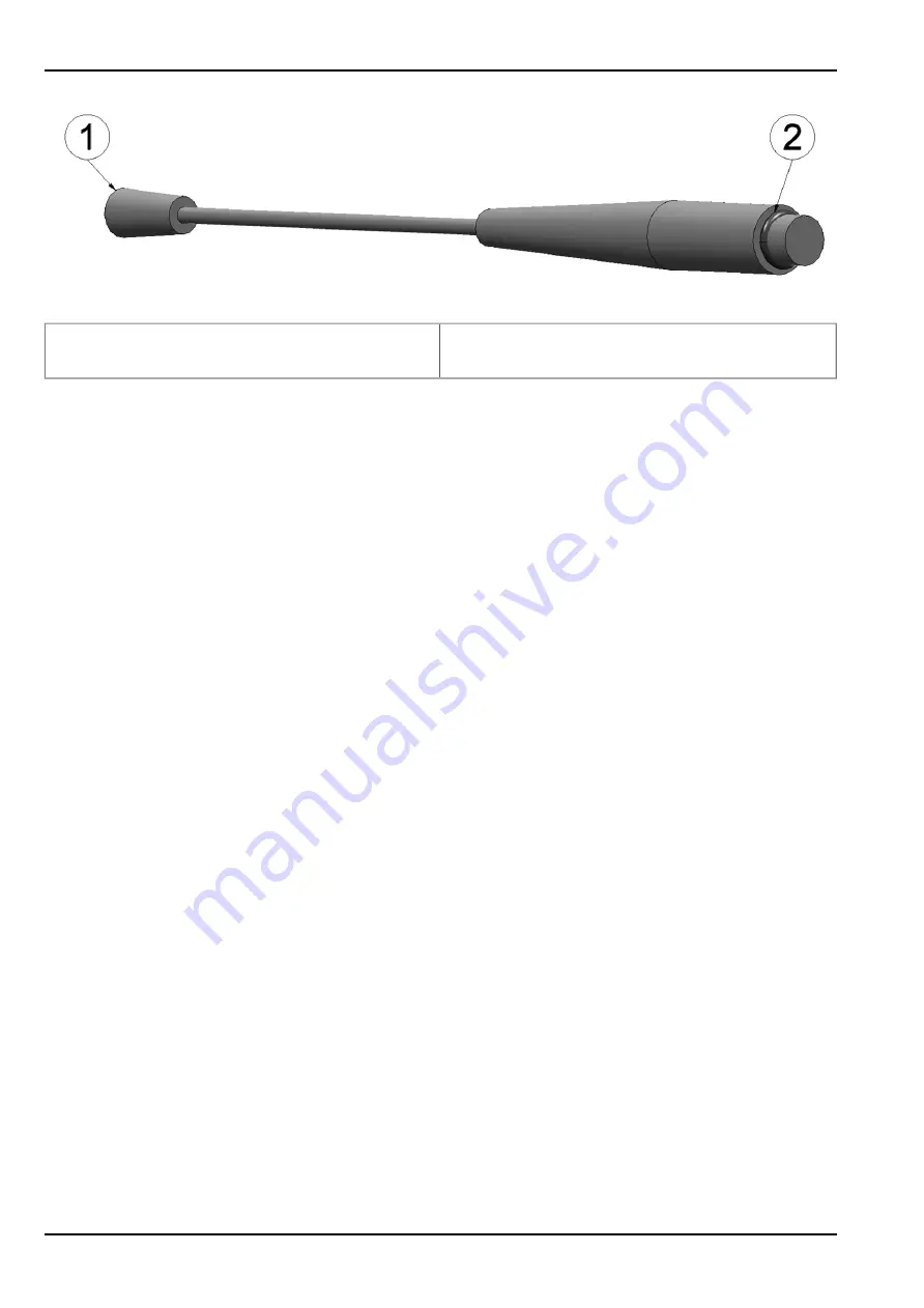
Antenna including assembled O-ring
1 Antenna 900 FME -F (206.801)
2 6.1x1.6 mm O-ring (included in the scope of
delivery of the 206.324 )
1. Assemble the O-ring on the antenna connector according to the Figure "Antenna including
assembled O-ring" on page 120.
2. The O-ring must be pressed firmly on to the antenna socket following assembly of the
antenna. Check the number of O-rings on the contact pin of the antenna socket.
Important note: Do not apply too much force when tightening the antenna. Tighten the
antenna or antenna extension by hand. Do not use a tool except for the plastic open-
ended spanner that is included in the myDatanet service kit (206.324 ) that will break
if the applied force is too strong.
11.6 Calibration
11.6.1 Calibration guidelines
Important note:
l
The calibration must only be completed by trained personnel.
l
The ESD safety guidelines must be observed during the calibration.
l
The calibration must not be completed in the Ex area.
11.6.2 Equipment required for the calibration
The following basic equipment is required:
l
A constant current source with an accuracy of more than 15 bit
l
A computer for the configuration program DeviceConfig
11.6.3 Calibration process
Note: All of the screenshots show version 4.6 of the DeviceConfig configuration program. The newer versions may
include minor changes to the appearance of the program.
120
Rev. 01


