Rev.
Date
Changes
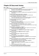
05
(2/4)
13.11.2020
(2/4)
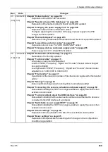
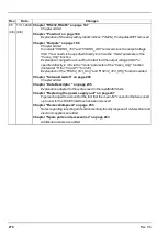
Chapter "Warranty" on page 27
Chapter added
Chapter "Disclaimer" on page 27
Chapter added
Chapter "Registration memory blocks" on page 36
Explanation of the fields "latestAppVersion", "installedAppVersion" and "appId"
removed.
Chapter "Transporting power supply units" on page 44
Information about the directive for ship transport corrected.
Chapter "Dimensions" on page 47
Figures changed to account for the fact that the 4-pin JST connector that was used
up to now for the RS485 interface has been removed.
Chapter "Assembling the myDatalogEASY V3 " on page 47
Figures changed to account for the fact that the 4-pin JST connector that was used
up to now for the RS485 interface has been removed.
Chapter "Connecting the sensors, actuators and power supply" on page 60
Figures and explanations changed to account for the fact that the RS485 interface
is parallel to universal inputs 3 and 4 on the main terminal block.
Figures and explanations changed to account for the fact that the 3,3V sensor
supplies on the interface and main terminal block can be switched separately from
one another.
Chapter "Connection examples" on page 64
Figure changed to account for the fact that the RS485 interface is parallel to
universal inputs 3 and 4 on the main terminal block.
Chapter "Technical details about the RS485 interface" on page 66
Notice added about the fact that the RS485 interface is only available if universal
inputs 3 and 4 are not being used.
Chapter "Technical details about the USB interface" on page 68
The rapidM2M Toolset has been replaced by the web-based development
environment rapidM2M Studio .
Link for free registration to the Microtronics Partner programme added.
Note changed to account for the fact that prior to establishing a USB connection
with a PC the antenna only needs to be removed if it is earthed or connected to the
ground potential of another object.
Chapter "Switchable sensor supply VOUT" on page 69
Figures and explanations changed to account for the fact that the sensor supply at
VOUT can be varied in the range 5...24V.
Chapter "Switchable sensor supply VEXT" on page 70
The
sensor supplies attached to the RS232 interface (VEXT
RS2323,3V ) and the main
terminal block (VEXT) can now be switched separately to each other.
Note removed stating that when connecting an extension module to the RS232
interface the sensor supply VEXT on the main terminal block can no longer be
used.
272
Rev. 05
Summary of Contents for myDatalogEASY V3
Page 2: ......
Page 13: ...Chapter 2 Declaration of conformity Chapter 2 Declaration of conformity Rev 05 13 ...
Page 14: ......
Page 42: ......
Page 76: ......
Page 88: ......
Page 102: ......
Page 110: ......
Page 116: ......
Page 234: ......
Page 244: ......
Page 252: ......
Page 254: ......
Page 266: ......
Page 276: ......

