Chapter 7 Installation
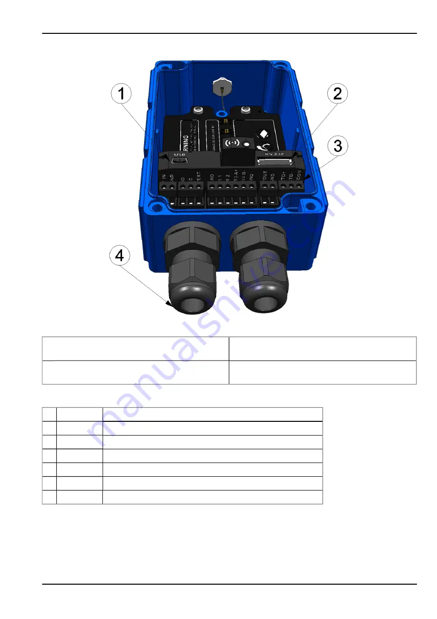
Connection of the sensors and power supply (view without power supply unit)
1
Mini-B USB (only for debug and script update)
3
Main terminal block (split into 2x 2-pin, 2x 3-pin, 1x
6-pin)
2
RS232 interface (7-pin JST connector)
4
Cable screw connection (cable diameter of 5-
10 mm)
1
SHIELD
Cable shielding
2
GND
Ground
3
RTS
RTS line of the RS232 interface
4
CTS
CTS line of the RS232 interface
5
RXD
RXD line of the RS232 interface
6
TXD
TXD line of the RS232 interface
7
VEXT
RS232
Switchable sensor supply (3,3V )
Assignment of the RS232 interface
Rev. 05
61
Summary of Contents for myDatalogEASY V3
Page 2: ......
Page 13: ...Chapter 2 Declaration of conformity Chapter 2 Declaration of conformity Rev 05 13 ...
Page 14: ......
Page 42: ......
Page 76: ......
Page 88: ......
Page 102: ......
Page 110: ......
Page 116: ......
Page 234: ......
Page 244: ......
Page 252: ......
Page 254: ......
Page 266: ......
Page 276: ......


