Chapter 8 Installation
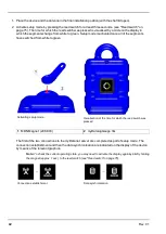
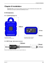
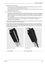
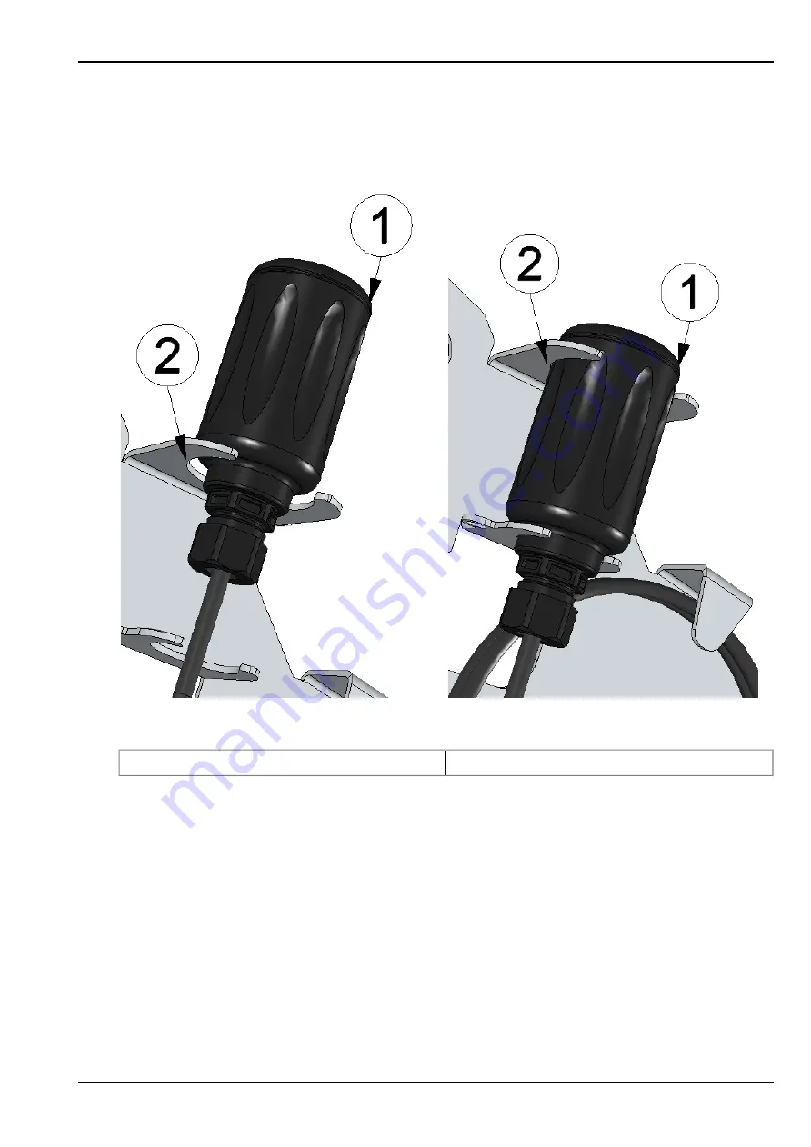
5. As illustrated in the following figures, guide the BLE Gauge into the relevant bracket of the mounting
fixture from above. Always ensure that the minimum permissible bend radius of 60mm is also
observed. It may be necessary to remove some of the connection cable from the cable holder again.
Inserting the BLE Gauge
BLE Gauge in final mounting position
1
Bracket for theBLE Gauge
2
BLE Gauge
6. Now hang the mounting fixture including the mounted BLE Gauge on the previously prepared screw
(see "Suspended installation – step 2" on page 52).
The following step is not mandatory.
7. Tighten the screw on which the mounting fixture is suspended.
Rev. 01
55
Summary of Contents for myDatalogGauge 3G
Page 2: ......
Page 10: ...2 2 BLE Gauge 10 Rev 01 ...
Page 11: ...Chapter 2 Declaration of conformity Rev 01 11 ...
Page 12: ......
Page 13: ...Chapter 3 Ex certification Chapter 3 Ex certification 3 1 BLE 3G Gateway ATEX Rev 01 13 ...
Page 14: ...14 Rev 01 ...
Page 15: ...Chapter 3 Ex certification Rev 01 15 ...
Page 16: ...16 Rev 01 ...
Page 17: ...Chapter 3 Ex certification 3 2 BLE Gauge Rev 01 17 ...
Page 18: ...18 Rev 01 ...
Page 19: ...Chapter 3 Ex certification Rev 01 19 ...
Page 20: ...20 Rev 01 ...
Page 134: ......
Page 140: ......
Page 152: ......
Page 154: ......


