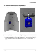
2. A connection to the BLE & 3G Gateway ATEX server is established if the BLE pairing between the
BLE Gauge sensor modules and the BLE & 3G Gateway ATEX was successful.
3. The data is synchronised with the myDatanet server.
8.3.2 Connecting the GSM antenna
Important note:
To ensure the correct functionality, only use antennas that are supplied by the
manufacturer.
The standard antenna is directly connected to the antenna connector (see "Overview" on page 27) of the
myDatalogGauge 3G .
1. Connect the connection cable of the antenna directly to the antenna connector of the myDatalogGauge
3G (see "Overview" on page 27).
The following step is not mandatory.
2. Check whether the connection to the myDatanet has worked correctly (see "Testing communication
8.3.2.1 Optimum antenna positioning for assembly in a shaft
8.3.2.1.1 Typical influences on the signal quality
Steel cover
up to -30dBm
Concrete cover
approx. -10dBm
Environmental influences
up to -15dBm
Installation height of the antenna
approx. -5dBm / depth of 15 cm
Vertical/horizontal alignment
approx. -10dBm
Horizontal alignment
up to -15dBm
Centre/edge of the shaft
approx. -10dBm
Other influences
Transmission power of the network operator
Signal losses compared to the reference measurement
62
Rev. 01
Summary of Contents for myDatalogGauge 3G
Page 2: ......
Page 10: ...2 2 BLE Gauge 10 Rev 01 ...
Page 11: ...Chapter 2 Declaration of conformity Rev 01 11 ...
Page 12: ......
Page 13: ...Chapter 3 Ex certification Chapter 3 Ex certification 3 1 BLE 3G Gateway ATEX Rev 01 13 ...
Page 14: ...14 Rev 01 ...
Page 15: ...Chapter 3 Ex certification Rev 01 15 ...
Page 16: ...16 Rev 01 ...
Page 17: ...Chapter 3 Ex certification 3 2 BLE Gauge Rev 01 17 ...
Page 18: ...18 Rev 01 ...
Page 19: ...Chapter 3 Ex certification Rev 01 19 ...
Page 20: ...20 Rev 01 ...
Page 134: ......
Page 140: ......
Page 152: ......
Page 154: ......

