Chapter 5 Functional principle
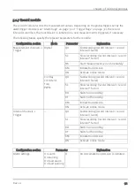
The following table specifies the relevant parameters for the module:
Configuration section
Mode
Parameter
Explanation
Measurement channels -
>Config.
Digital
Decay
Temporal function in the measurement
cycle
Time
Time x, that is used for decay modes
"up" "down" and "up & down"
Cnt.Day
---
---
Cnt.Intervl.
Freq
PWM
Decay
Temporal function in the measurement
cycle
Time
Decay period. Up to a maximum of 60
measurement valuescan be used for the
calculation (e.g. 1 channel:
60 measurement values; ... 4 channels:
15 measurement values each). To
calculate the number of measurement
values that are taken into account, refer
to "Example to clarify the record interval,
measurement cycle and burst interval in
conjunction with the decay" in chapter
"Basic setting" on page 73.
5.1.5 Hold module
With the help of the hold module, it can be determined how to proceed in the event of invalid
measurement values. It ensures the last valid measurement value is retained until a new valid
measurement value is available or passes the error on after a certain number of invalid
measurements. The hold module is only available for the universal inputs in the "Freq" and "PWM"
channel modes.
The following table specifies the relevant parameters for the module:
Configuration section
Mode
Parameter
Explanation
Measurement channels -
>Config.
Digital
---
---
Cnt.Day
Cnt.Intrvl.
Freq
Hold
Hold the last valid measurement value
for x measurement cycles
PWM
Rev. 01
29
Summary of Contents for myDatalogNANO Ex
Page 2: ......
Page 8: ......
Page 9: ...Chapter 2 Declaration of conformity Chapter 2 Declaration of conformity Rev 01 9 ...
Page 10: ...2 1 Declaration of conformity Appendix 10 Rev 01 ...
Page 11: ...Chapter 2 Declaration of conformity Rev 01 11 ...
Page 12: ......
Page 24: ......
Page 52: ......
Page 78: ......
Page 86: ......
Page 92: ......
Page 104: ......
Page 108: ......
Page 110: ......


