DX-2200
– SD/HD-SDI Text & Graphics Inserter – User Manual
Page 19 of 103
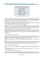
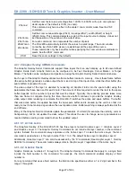
Figure 9: DX-2200-TI Layer Order
The top layer in the mix is referred to as
Graphics Text Layer 1.
This layer displays up to 48 Fields that
support text and graphics. The optional Frame Counter displays on this layer. Text Fields on this layer are
configured using either the Text Overlay Serial Commands or the Graphics Overlay Serial Commands. The
Frame Counter is configured by the Frame Counter Serial Commands.
The next two layers are
Graphics Layer 2
and
Graphics Layer 3
. These layers each display up to 48 display
Graphic Fields that are controlled by the Graphic Overlay Serial Commands.
The 4
th
layer is the
SDI video
, and the 5
th
layer is the
Black Background.
Within any one layer, no mixing of fields takes place. If two fields have pixels that occupy the same
coordinates, one will overwrite the other. When an update is performed to render the fields on a layer, the
fields are rendered in order of their field number. For example, Field 4 will always be rendered after Field 3
and will overwrite any pixels of Field 3 if they are in the same location in the frame.
When graphic fields on different layers are placed at the same coordinates, they mix according to their
transparencies and the layer order. When a field is fully visible, no content that is on the layers below it will
be visible. When the field is partly or fully transparent, it mixes with the layers below according to their
transparencies.
4.8 SERIAL & MANUAL Control
The SD/HD-SDI Video Text Inserter has two methods of control: SERIAL Control using the RS232 port, and
MANUAL Control using the DIP switch and Toggle switch. SERIAL Control allows control full of the
capabilities of the DX-2200-TI, and MANUAL Control provides a subset of functions.
SERIAL Control is always active. In the factory default configuration the Toggle Switch and DIP switch are
active.
The functions of the DIP switch and Toggle switch can be reconfigured by SERIAL Control commands to
customize the Switcher so that the controls provide the set of functions required for a specific user
application. The modified configuration can be saved on board in the flash configuration memory.
4.8.1 SERIAL Mode of Operation
When SERIAL control is used, the DX-2200-TI is controlled via commands sent to the DB9 Serial Control
Port.
The serial COM port of the computer connected to the DX-2200-TI should be configured for: 115,200 baud,
1 stop bit, and no flow control.
4.8.1.1 USB 2.0 to RS-232 Serial Port Adapter
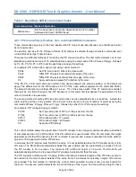
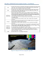
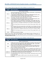
The DX-2200 product is supplied with a
USB 2.0 to DB9 RS-232 Serial Port Adapter Kit
(PN: 811-USB-
RS232 Kit) to connect the DB9F Serial Port to a USB 2.0 port of a PC or laptop. The Kit consists of a USB
Summary of Contents for DX-2200
Page 87: ...DX 2200 SD HD SDI Text Graphics Inserter User Manual Page 87 of 103 ...
Page 92: ...DX 2200 SD HD SDI Text Graphics Inserter User Manual Page 92 of 103 ...
Page 97: ...DX 2200 SD HD SDI Text Graphics Inserter User Manual Page 97 of 103 ...
Page 100: ......
Page 101: ......
Page 102: ......
Page 103: ......


