Installer Manual
Microvideo srl
www.microvideo.eu
16
Chapter 2 –Modules Description
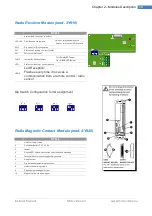
Radio Receiver Module (mod. SY910)
SY910
System BUS connector (Can Bus)
JP3-JP4
CAN Bus end line jumpers
Chiuso = terminazioni inserite
Aperto = terminazioni NON inserite
SW5
Dip-switch for ID configuration
DL3
Status Led Flashing = correct function
DL1
Future use (Not used)
TAMP
Jumper By-Passing tamper
Off = ENABLED Tamper
On = DISABLED Tamper
LED1
Status Led flashing = correct function
LED2
Led Reception:
Flashes every time it receives a
communication from a remote control / radio
sensor
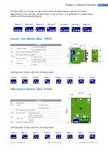
Dip Switch Configuration for ID assignment
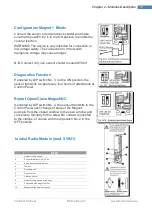
Radio Magnetic Contact Module (mod. SY920)
SY920
1
Holes for fixing screws
2
Connector Battery 3.6 V 2.4 Ah
3
tamper
4
Report LED: lights whenever the module sends a message
5
Terminal block for connecting auxiliary sensors
6
Reed Contact
7
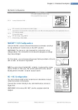
Dip-Switches programming functions
8
Holes for base fixing screws
9
Pegs closing the magnet holder
10
Magnet Holder Lid with magnet
Summary of Contents for Synergy SY800
Page 1: ...1 ...
Page 60: ...Installer Manual Microvideo srl www microvideo eu 60 ...

