background image

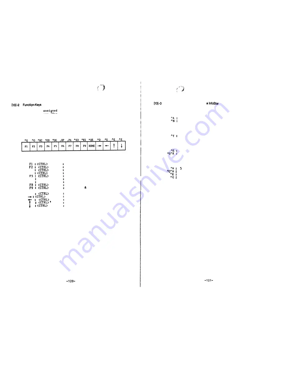
 Assignment for WordStar

W e   h a v e  

  a l l   F u n c t i o n - K e y s   s p e c i a l l y   i n   o r d e r   t o

make easy to use

WordStar’ a p p l i c a t i o n   p r o g r a m   w i t h o u t   u s i n g

original keys commands.

T h e r e f o r e   y o u   s h o u l d   f o l l o w   b e l o w   m e n t i o n e d   t a b l e   t o   u s e

the assigned Function-Keys and commands.


  ‘ Q ’


  ‘ 0 ’

F3 


‘ O C ’

F4  

  ‘ O D ’


  ‘ O G ’

F6 

.OP <RETURN>

F7 

. PA <RETURN>


  ‘ K D ’


‘ K S ’

HOME 

  ‘ Q E ’


  ‘ D ’


 ‘S’

    E ’


  ‘ X ’

Quick menu

On screen menu

C e n t e r   t e x t

P r i n t   d i s p l a y   o n / o f f

Paragraph tab

Omit page number

Change page

F i l e s   s a v e   - -   d o n e

Files save   resume

M o v e s   t h e   c u r s o r   t o   t o p   l i n e

M o v e s   t h e   c u r s o r   r i g h t   o n e   c h a r a c t e r

M o v e s   t h e   c u r s o r   l e f t   o n e   c h a r a c t e r

M o v e s   t h e   c u r s o r   u p   o n e   l i n e

Moves the cursor down one line

Option Commands for WordStar   

 SYSTEM

1.

B o l d   f a c e   ( F P - 8 0   f u n c t i o n )

  B o l d   f a c e   o n

  B o l d   f a c e   o f f

2.

U n d e r   s c o r e   ( F P - 8 0   f u n c t i o n )

  U n d e r   s c o r e   o n / o f f   ( t o g g l e )

3.

I t a l i c

  I t a l i c   o n

  I t a l i c   o f f

4.

C h a r a c t e r   p i t c h


 cpi


  8   c p i   ( b o l d   f a c e )


10 cpi


1 7   c p i   ( b o l d   f a c e )

Summary of Contents for Formula-1

Page 1: ...PORTABLE COMPUTER USER S MANUAL 9 Comrjuter System En heering liliC 1Qvo cZ CbXRACiOIl Shinei Bldg 8 5 Nishishinjuku 3 chome Shinjuku ku Tokyo 160 JAPAN Telephone 03 3774661 Telex 2325279 MVOICE J ...

Page 2: ...mer PI 9 K e y b o a r d ES 10 S e r i a l I O P o r t s S 11 P a r a l l e l I O P o r t s 6 1 Expansionfnterface SpecificationsLIIIIIIIIIIIIIIIIIIIIIIIIIIIIIII w 1 5 25 Expansion Floppy Disk Drives FD 5 m m W 2 8 E x p a n s i o n F l o p p y D i s k D r i v e s F D 8 Nl 3 C e n t r o n i c s S t a n d a r d P r i n t e r I n t e r f a c e F P 8 0 m w RI 4 R S 2 3 2 C I n t e r f a c e U 5 B i g...

Page 3: ... Ill 7 7 KBSTS System s Keyboard Status Check 63 ll 7 8 LPRINT C e n t r o n i c s S t a n d a r d P r i n t e r C o n t r o l 7 4 II 7 9 UCRT R S 2 3 2 C C h a n n e l B D a t a O u t p u t wwwwwwwwww 74 11 7 10 UKD R S 2 3 2 C C h a n n e l B D a t a I n p u t wwwwwwwwwww 75 ll 7 11 USIOTN RS 232 C Channel A Data Input wwwwwwwww 75 11 7 12 USIOOUT R S 2 3 2 C C h a n n e l A D a t a O u t p u t ...

Page 4: ...ms of different architecture can keep mutual transferability as long as they are based on the CP M 80 Operating System The CPU of this computer is 280A which enables high speed processing The memory of the Formula l being equipped with RAM 64K bytes along with Boot Strap ROM 4K bytes RAM is 64K bits x 8 dynamic RAM and all of the 64K bytes memory spaces are used for user programmable area Boot Str...

Page 5: ...on Loaded with EP ROM Programmer enables you to write in and read out 4 kinds of EP ROMs 2716 2516 2732 2532 and 2764 on t h e CP M 80 basis 7 All the necessary devices are packed in one case m i n i a t u r i z e d a n d l i g h t e n e d t o b e p o r t a b l e s u f f i c i e n t for data processing purposes 8 The CP M 80 is used as an Operating System of the Formula l 9 Various kinds of applic...

Page 6: ...emory Memory to I O DMA Transfer d 5 Floppy Disk Drive 5 25 two sided double density x 2 units 358K b y t e s d i s k d r i v e 1 2 8 bytes sector FM 256 bytes sector MFM 18 sectors track Type of Disk Drive Capacity D a t a B y t e s S e c t o r Sectors Track 3 D M A Device Mode Functions Z80A DMA Byte cycle steal Burst Mode Data transfer between 2 Ports I O or Memory Search of 8 bits data Cylinde...

Page 7: ... Paper 127 W x 65 Dia mm roll paper No TP 5OCA127 by Jujo Seishi Underline blinking 16 frames interval Cursor Mode Method Video RAM Capacity Character Generator Character Code Interface Non interlace mode Video RAM method I O map 5 8 EP ROM Programmer 2K bytes static RAM EP ROM 2716 Intel 2516 TI 2732 Intel 2532 TI 2764 Intel 2K bytes EP ROM ASCII However programming voltage for 271612516 2732 is ...

Page 8: ... keys are changed to shift mode Function Keys Fl FZ F3 F4 e FS F6 s F7 F8 B F9 I These key codes are assigned 8 bytes by FUNC command of System Utility Program HOME t 1 Scanning Method Hardware Scanning Inter Lock N Key roll over Character Generator 2K bytes EP ROM These cursor control key codes are assigned 2 bytes by FUNC command of System Utility Program A t t h e f i r s t t i m e t h e s e k ...

Page 9: ...C h a n n e l B RS 232 C or 20mA Current Loop W h e n T r a n s m i t t i n g R e c e i v i n g b u f f e r i s a t s t a t e o f r e a d i n e s s I t fs p o s s i b l e t o input to CPU DMA transfer request by s p e c i f i c p r o g r a m Break Out of Interrur tion Vector by the f o l l o w i n g condition an are o n l y p o s s i b l e w i t h s p e c i f i c p r o g r a m I n t e r r u p t i ...

Page 10: ...t the byte input mode Receiving strobe signal for input or o u t p u t f r o m t h e e x t e r n a l d e v i c e s a t the byte bi directional mode When the conditions are true at the state of bit mode 6 Expansion Interface Specifications The Formula l s Expansion Interface Specifications are a s f o l l o w s 5 2 5 f l o p p y d i s k drives FD 5 8 floppy disk drives FD 8 Centronics Standard Inte...

Page 11: ...t respectively The layout of the rear view is as follows The DMA transfer requests Break Out by the in c o m i n g m s i g n a l f r o m o u t s i d e t h e s y s t e m u n i t Therefore it is possible to input to CPU DMA transfer requests by specific program B r e a k O u t o f I n t e r r u p t i o n V e c t o r b y t h e following conditions are only possible with specific program Fan O 0 Inter...

Page 12: ... assignment and the signal name are on the following page Table 2 C o n n e c t o r S i g n a l of 8 F l o p p y D i s k D r i v e Type of Disk Drive 8 two sided double density Capacity 997K b y t e s Data Bytes Sector 128 bytes sector FM 256 bytes sector MFM Sectors Track 2 6 s e c t o r s t r a c k Cylinders Disk Drive 7 7 c y l i n d e r s d i s k d r i v e I INDEX PULSE I Tracks Disk Drive I54...

Page 13: ... s are shown i n t h e f o l l o w i n g page Fig 4 L o g i c o f P a r a l l e l I O P o r t s B e s i d e s t h e o t h e r s i g n a l s t h e P a r a l l e l I O P o r t s p o s s e s s t h e s i g n a l s o f Dm m m The e x p l a n a t i o n o f t h e s e s i g n a l s a r e a s f o l l o w s 1 m DMA REQuest Input T h i s s i g n a l i s a c t i v e L o w Parallel I O for DMA transfer and ava...

Page 14: ...1 1 2 I N2b 3 l 9 ARDY r bi SN75452 I CHANNEL B BAUD RATE ZC T02 CK TGZ v 5v 3M 7 lmx8 1 3 M2b v5 Blank Blank I 3 I 17 A 18 Z80A PI0 B7 B6 Z80A 1 2288MHz 153 6KHz CTC COUNTER CLOCK 1 ACK BUSY 1 2288MHz 153 6KHz COUNTER CLOCK 2 CK TGO ZC TOO B5 B4 CK TG3 CTCCLK 83 82 Bl BO I 1 SN75452 l I II BRDY BSTB Fig 5 Logic of Counter TJmer HaEQ TRT CTCCLK 23 YY I 1 G I 231 I I Fig 4 Loaic of Parallel I O Por...

Page 15: ...und I 11 I1 4 I BUSY II 29 I 12 I SG I I 12 I 15 I PEHP II 30 I 12 I SG I 1 12 SG I I Signal Ground I I 13 I 16 13 ACK End of Operation IN P I O B 7 I 14 1 BUSY Under Operation IN P I O B 6 1 II 3f I I 15 I PEMP p of Paper 1 IN PIOB5 1 I 16 1 r Printer Ready IN 1 PIOB4 36 Unused Unused 1 Reset PIOB3 PIOBZ I OUT 1 PIOBl I SG Signal Ground I PIOBO I Data Strobe I 3m P I 1 I I 30 RMxx Insulated Flexi...

Page 16: ...2 I 24 17 15 RS ER ST 1 RT ST 2 Further i t i s p o s s i b l e t o s e t t h e B a u d R a t e f o r e a c h channel independently For detail see the item No 9 B a u d R a t e S e t t i n g You can refer to Fig 6 L o g i c o f S e r i a l I O P o r t s w h i c h s h o w s t h e c i r c u i t o f t h e S e r i a l I O P o r t s About the pin assignment of the connector and the signal name see Tabl...

Page 17: ...P 1 20mA Current Loop Send Data t I I l3 I l I T 14 I 15 ST 2 Send Timing From MODEM I 15 I ST 2 I Send Timing From MODEM 1 17 RT Receive Timing 17 RT I Receive Timing I L 18 L 19 ER Data Terminal Ready L 3 21 22 21 Ic 22 23 4 23 RDCLPM 20mA Current Loop Receive Data 0 I 24 I ST1 1 Send Timing To MODEM I I 24 I I Send Timing To MODEM I I ST1 1 I I I I I 1 25 1 SDCLPM 1 20mA Current Loop Send Data ...

Page 18: ... k e t t e s a s per your requirement For your information when using FD 5 or FD 8 with Formula l you do not need to set physical address The terminator has already been detached from the disk drives Because this is being set as per our company s standard peripherals to use simultaneously with Formula l However you may have to refer Table 7 Expansion Floppy Disk Drives Address time to time to use ...

Page 19: ...k Drive In Use Power Switch ON OFF FIR 11 t FD 8 Floppy Disk Drive FOR 9 FD 5 Floppy Disk Drive r Q 0 O 0 r 0 0 fH Gray Color AC Power Note 1 Note 1 Fig 12 FD 8 Cable Connection Ffg 10 FD 5 Cable Connection 29 280 ...

Page 20: ...ere being no exhaust fan in the disk drives FD 5 FD 8 therefore to refrain from over heating you should put it OFF when not using Do not put anything paper books heavy manuals diskettes etc on the drives in order to have proper v e n t i l a t i o n I71 3 FP 80 External Printer Connection Roller Knob Fig 1 3 FP 80 External Printer P a r a l l e l I O Connector Printer Connector FOR 14 FP 80 Cable ...

Page 21: ...nt Clock as Transmitting Clock 1 SIO Channel B JP4 I I 2 3 Used Ext Clock as Transmitting Clock i SIO Channel B 1 2 RS 232 C bJP3 2 3 20 mA Current Loop SIO Channel B SIO Channel B l 2 Used Counter Output of Channel O CR Channel 3 as a Clock Input of CTC Channel 3 Counter Mode JP6 b 2 3 Used Ext Clock as a Clock Input CTC Channel 83 of CTC Channel 83 Counter Mode I SIO Channel B Receiving I I SXO ...

Page 22: ...COOOH 4800 1 OFF 1 ON 1 OFF 1 OFF 9600 ON OFF OFF OFF ON 19200 OFF OFF OFF OFF ON FsooH I 300 11 ON 1 ON 1 ON 1 OFF When IPL operates the contents of Boot Strap ROM are transferred in this area FF FFH I 600 IIOFFION ON ION 1 OFF 1 I 1200 110 I oN 10 4 IOFF 1 F i g 1 5 M e m o r y A l l o c a t i o n I 2400 IIOFFIOFF ON ION 1 OFF 1 Synchronous Only when setting the Power ON or the system is reset t...

Page 23: ... appear on your CRT and the Boot Strap program being loaded to the main memory from the system diskette F o r m u l a l I P L V e r s f o r m i n i 2D The Boot Strap program is loaded to the following address 256 bytes System Parameter System Area U s e r s A r e a CCP Area m m m a BDOS Area I BIOS Area L II I O Control Area System Diskette Side 01 02OOH t Track 0 S e c t o r 1 J 53K b y t e s Fig...

Page 24: ...e c a n k e e p m u t u a l t r a n s f e r a b i l i t y a s long as they are based on the CP M 80 Operating System Therefore o l d l i b r a r i e s a s w e l l a s k n o w h o w s a l r e a d y f i l e d i n can be used easily See the CP M 80 OPERATING SYSTEM MANUAL for details of the CP M 80 commands The Formula l can use various kinds of application software packages on the CP M 80 basis avai...

Page 25: ...y contents in a file Following are the I O Device Operation TYPE Type the contents of a file on the logsed disk 1 Read a Console Character Write a Console Character Read a Sequential Tape Character Write a Sequential Tape Character Write a List Device Character Get or Set I O Status Print Console Buffer Read Console Buffer Interrogate Console Ready The following is transient commands of the CP M 8...

Page 26: ... 19 Delete File 20 Read Sequential 21 Write Sequential 22 Make File 23 Rename File 24 Return Login Vector 25 Return Current Disk 26 Set DMA Address 27 Get Addr Alloc 28 Write Protect Disk 29 Get R O Vector 30 Set File Attributes 31 Get Addr Disk Parms 32 Set Get User Code 33 Read Random 34 Write Random 35 Compute File Size 36 Set Random Record 37 Reset Drive 40 Write Random with Zero Fill The phys...

Page 27: ...Drive 3 Drive A and Drive B are mounted on the system unit 440 11 5 BIOS The BIOS must be changed to implement the CP M 80 on the Formula l The BIOS made by our company supports the floppy disk drive of 5 25 two sided double density 8 two sided double density and 8 one sided single density Refer to the item No ll 4 Expansion Floppy Disk Drives for detail allocation of the disk drives Be careful of...

Page 28: ...Printer Control Parallel I O Port Sector 3 6 s e c t o r s t r a c k 1 2 8 b y t e s s e c t o r Disk Capacity 346 5K bytes except the system track i 8 F51 SH UCRT RS 232 C Channel B Data Output 9 F518H UKB RS 232 C ChannelkB Data Input 10 FSlBH USIOIN RS 232 C Channel A Data Input 11 F51EH USIOOUT RS 232 C Channel A Data Output 11 6 2 8 Two Sided Double Density Diskette 1 Format of Diskette Cylin...

Page 29: ... a m e t e r l e n g t h a n d c o n t e n t s 2 Now you look at the Table 16 Memory Allocation of FDC Program Parameter 3 I n s e r t CP M d i s k e t t e i n t o d r i v e A 4 Type DIR press RETURN Get directory of the drive A 5 Look for ED COM file as Editor command file 6 Now type ED EXAMPLE ASM press RETURN For detail p l e a s e r e f e r t o o u r F o r m u l a l s CP M 80 OPERATING SYSTEM ...

Page 30: ... Program Load This program is used only at the system starting to i n i t i a l i z e t h e s y s t e m I O c o n t r o l l e r loads the system program from the floppy diskette to the main memory When you call this program the Formula l becomes at a initial state through Software Reset Usually there is no need to use this program II 3 FDC Floppy Disk Control Input Parameter 13 bytes of parameter ...

Page 31: ... 3 0 o r some other number in between 129 bytes to 255 bytes t h e n i t i s a u t o m a t i c a l l y b e i n g s e t t o 2 5 6 b y t e s When the transfer data length exceeds the capacity of t h e l a s t s e c t o r o f t h e t r a c k t h e t r a c k n u m b e r i s renewed except for the Track O Side 0 or the l a s t t r a c k When you intend to retry executing expansion command usually alway...

Page 32: ... Track Number 1 FFFO t 2 I Sector Number I Contents of Error FFFO t 3 I Number of Transfer Bytes low 7 I olololo I Normal ending of command I FFFO t 4 I Number of Transfer Bytes High I 0 0 0 1 Normal ending of command In case of reading data field with deleted data address mark I 0 0 1 0 SEEK ERROR FFFO t 5 Transfer Address Low ba FFFO t 6 Transfer Address High 7 FFFO t 7 Retry Mode 02 H FFFO t 8 ...

Page 33: ... Cursor E r a s e l i n e A f t e r C u r s o r M 4DH W h e n c u r s o r a t t h e l a s t l i n e i f t h i s program accept LF code at this time cursor a u t o m a t i c a l l y g o e s t o t h e f i r s t l i n e Clear screen and screen does not scroll up e v e n i f a f t e r a c c e p t i n g L F c o d e BEL 07H Beep the alarm BS 08H M o v e t h e c u r s o r o n e c h a r a c t e r t o t h ...

Page 34: ...nated and in the second byte column number The next page shows the cursor addressing code I n c a s e o f the MC s e q u e n c e i f d e s i g n a t e d b y t e numbers are not minimum 2 bytes which is unacceptable to program and therefore the regular display mode does not return to main program P r i n t o u t c o n t e n t s o n l y f r o m t h e s y s t e m s t h e r m a l w i n t e r 58 I 1 I ...

Page 35: ...ers when the characters are over 80 or the device receives the CR OD H code t h e p r i n t e r s t a r t s p r i n t i n g b e c a u s e t h e p r i n t e r c a n n o t print each and every character Below we provide detail information pertaining to system s t h e r m a l p r i n t e r c o n t r o l c o d e s v BS 08H C a n c e l t h e l a s t c h a r a c t e r before BS c o d e T h i s c o d e i...

Page 36: ... s a r e r e s e r v e d e x c e p t A r e g i s t e r F l a g r e g i s t e r Calling Method CALL KB FSOC H By calling this program a f t e r k e e p i n g k e y c o d e s i n t o Accumulator A register and returns back to main program A l l r e g i s t e r s e x c e p t A r e g i s t e r b e i n g r e s e r v e d At the time of calling BDOS Function the key codes of Function Keys Cursor Control ...

Page 37: ...V B N M REPT SHIFT _ t H TAB CAP SHIFT LOCK LOCK DEL ESC 1 0 9 6 Fig 18 Keyboard Layout 1 1 2 There is no output of key code if you hit this Key 1 The system is reset by means of hitting this key with CTRL key 2 The FEED key forward the roll paper of the printer c 76 77 78 79 80 81 82 83 84 85 86 87 88 89 90 91l 56 I 57 I 58 I 59 60 61 I I Fig 18 Keyboard Layout 2 s I 62 63 64 65 66 67 68 69 71 72...

Page 38: ...1 j 6C j L 1 4C FF 1 OC FF CC 1 SPACE SPACE SPACE SPACE L 115 Q 71 Q 51 DC1 11 DC1 11 139 1 t 1 3B 1 2B 1 88 1 1 8B I40 1 3A 1 1 2A 1 16 w 77 W 57 ETB 17 ETB 17 17 e 65 E 45 ENQ 05 ENQ 05 I 41 I 1 I 5D I 1 I 7D I 42 REl URN OD RETURN OD RETURN OD RETURN OD 43 SHIFT SHIFT SHIFT SHIFT L 1 18 r 72 R 52 DC2 12 1 DC2 12 b I 19 t 74 T 54 DC4 14 DC4 14 1 44 1 2 1 7A j Z 1 5A 1 SUB 1 1A 1 SUB 1 1A 1 120 Y...

Page 39: ...9 i I 5 I A5 I I B5 I I c5 1 c5 70 6 A6 B6 C6 C 6 71 1 Al Bl Cl C l 72 2 A2 B2 c2 c2 Table 19 Keyboard Code Capstan Lock Off 3 680 82 F6 96 96 96 96 i 83 F7 97 97 97 97 84 98 98 F8 98 98 85 F9 99 99 99 99 86 HOME 9A 9A 9A 9A 87 9B 9B 9B 9B 88 9C 9c 9c 9c 89 t 9D 9D 9D 9D 90 J 9E 9E 9E 9E 91 FEED FEED FEED FEED 1 T a b l e 1 9 Keyboard Code Capstan Lock Off 4 69 ...

Page 40: ...n s h i f t I Shift I Control 1 Shift Control 1 29 30 CTRL CTRL I CTRL CTRL A 41 a 1 61 SOH 01 SOH 01 I IF I 37 K I I E J k 6 B VT 08 VT OB 138IL 14C 11 16CI FF IOC FF IOC H4039 38 3A 2B2A 88 8A 88 8A 1 41 1 1 1 5D I 1 I 7D I 142 IREURN OD 1 RETURN1 OD 1 RETURN1 OD 1 RETUPNj OD 1 1 43 SHIFT 1 1 SHIFT 1 1 SHIFT 1 I SHIFT 1 1 44 2 1 SA 1 z 1 7A SUB 1 1A 11 SUB 1 1A 1 45 x 38 x 78 CAN 18 CAN 18 8 46 ...

Page 41: ...09 1 I 84 F8 98 98 i 98 98 a5 F9 99 99 p d 99 r I v I1 Table 19 Keyboard Code Capstan Lock On 4 160 1 DEL 7F DEL 7F DEL 7F DEL _ 7F c r 61 ESC 1B ESC 18 1 ESC 1B ESC 18 62 AA BA CA CA I L k I 63 AD BD CD CD 7 D I 64 CL AB BB CB CB I 66 8 A8 Ba c a c 8 67 9 A9 B9 c9 c9 1 4 68 4 A4 B4 c4 c4 i P9 I 5 I A5 i t B5 I I c5 c5 I I k T 70 6 A6 B6 C6 C6 71 1 Al 81 C1 Cl I v 82 c2 c2 a m 72 2 A2 I I L Table ...

Page 42: ... data into A register which you intend to output from Channel B Output Parameter Set a input data from Channel A i n t o A r e g i s t e r Output Parameter Not exist Register A l l r e g i s t e r s a r e r e s e r v e d e x c e p t A r e g i s t e r F l a g r e g i s t e r Register A l l r e g i s t e r s a r e r e s e r v e d Calling Method CALL USIOIN FSlB H Calling Method CALL UCRT FSlS H This...

Page 43: ... R e c e i v e r Buffer Ready status The RS 232 C Channel B Input Status being assigned to TTY Input Status when running on CP M 80 769 II 7 16 USIOISTS RS 232 CChannel A input Status Check Input Parameter N o t e x i s t O u t p u t P a r a m e t e r Without data A r e g i s t e r 00 H Z Flag 1 With Data A r e g i s t e r FF H Z Flag 0 R e g i s t e r All r e g i s t e r s a r e r e s e r v e d e...

Page 44: ... u d o n o t w i s h t o s t a r t o r i n t e n d t o r e t u r n t o i n i t i a l s t a t e p r e s s N k e y o n l y Further d u r i n g t h e p r o c e s s o f f o r m a t t i n g i f t h e r e b e i n g an e r r o r the following error message will appear on your CRT and gets back to initial state A FORMAT RETURN Diskette formatting Vers Drive name 3 A B C D E F G H or RETURN to reboot Forma...

Page 45: ... a t t i n g s t a r t 1 Y N Press Y for Yes Formatting start Read check start P r o c e s s c o m p l e t e This is the end of formatting of a new diskette In order to continue formatting more diskettes please refer to Note 2 8 For finishing this process Press RETURN in order to reboot Note 1 1 When using Disk Drive A B C and D 5 25 diskettes the track numbers will be from 00 to 39 due 40 t r a c...

Page 46: ...SGEN VERSION SOURCE DRIVE NAME OR RETURN TO SKIP Type source drive name as A and press RETURN You can use any one of the following drives name A B C D 820 6 You will get following message on your CRT SOURCE ON A THEN TYPE RETURN 7 Press RETURN You will get following message on your CRT FUNCTION COMPLETE This means process of reading from source diskette being completed 8 You will get following mes...

Page 47: ...2 2 S y s t e m g e n e r a t i o n f o r F o r m u l a l Destinat ion drive name A B C D or RETURN to reboot In the above state i n s e r t a n e w d i s k e t t e i n t o o t h e r d r i v e and lock Now input the name of the disk drive in which you have inserted the new diskette and press RETURN Due 5 25 diskettes being loaded by IPL therefore we only need to do SYSTEM of 5 25 diskettes and not...

Page 48: ...e name A B C D or RETURN to reboot Press B 860 870 5 After displaying Generation Start 3 Y N Press Y for Yes Generation starts and completes automafically following message appearsr Process Complete In order to continue SYSTEM more diskettes please refer to Note 2 6 Press RETURN in order to reboot Note 1 Important At first you should FORMAT a new diskette then proceed for SYSTEM the same When usin...

Page 49: ... A on your CRT Type PROMW and press RETURN You will get following command menu 88 I A PROMW RETURN Formula l EP ROM Programmer Vets I B 2 7 1 6 2 5 1 6 C 2 7 3 2 D 2 5 3 2 E 2 7 6 4 1 I Command Menu CM Compare Memory To EP ROM CP Copy EP ROM To EP ROM DP Memory Dump DT Display Command Menu EC Erase Check To EP ROM LR Linking Read From EP ROM To Memory MC Memory Change MF Make CP M Hexa File EP ROM...

Page 50: ...O 37FF ERROR I PI J i i 2 CP Copy EP ROM To EP ROM By this command the contents of the designated EP ROM are copied to the other designated EP ROM However you should note that only the same type of the EP ROM can be copied The following explains an input format of this command WI A Type of EP ROM RETURN 1 2 1 Command name CP 2 B C D or E P CP c RETURN COPY 2732 SET PROM ON THE SOCKET OK THEN HIT A...

Page 51: ... Parameter 1 1 Command name DT B 2716 C 2732 Dm2532 E 2764 CM CP DP DT EC LR MC MF z MM RD or Command Menu WW Compare Memory To EP ROM Copy EP ROM To EP ROM Memory Dump Display Command Menu Erase Check To EP ROM Lfnking Read From EP ROM To Memory Memory Change Make CP M Hexa File EP ROM Make CP M Hexa File Memory Read From EP ROM To Memory 3 f nm aO rL EF yq C _ T n IVnmnry c14c F w 5 EC Erase Che...

Page 52: ...mand WI Memory Address RETURN 1 2 1 Command name MC 2 He xa 4 characters P MC 4000 RETURN 4000 00 55 RETURN 55 A changing data 4001 00 RETURN Address increment 4002 00 RETURN 4003 00 RETURN 4002 00 RETURN Address decrement 4001 00 RETURN 4000 55 RETURN a Return command When you press RETURN key only this command will display the next forward address f However key and then press RETURN key if you p...

Page 53: ...key i n o r d e r t o m a k e t h e f i l e PI 96 p 10 RD Read From EP ROM To Memory This command simultaneously reads the contents of the EP ROM and loads it into the designated memory address The input format of this command is as follows WI EP ROM Type 1 Start Address RETURN 2 3 1 Command name RD 2 B C D or E 3 Hexa 4 c h a r a c t e r s P RD B 5000 RETURN READ 2716 ADDRESS 5000 SET PROM ON THE...

Page 54: ... result appears You should note that the erase check has not been done at this time of writing If error occurs in the process of writing this command rewrites again automatically In order to stop writing on the way press S key to finish writing press N key and at this state the process compare check does not take place In order to continue writing aga n press Y key The writing address and the rela...

Page 55: ...ystem Program into Drive A 2 You will get prompt A on your CRT 3 Type DIR press RETURN Key to get the directory of the CP M 80 4 Now you check in the directory for Function Keys codes change command as FUNC COM 1 oo 5 Type FUNC press RETURN key 6 You will get above message on your CRT Fig 23 There are four different types of command in order to change Function Keys codet 1 ASCII code input command...

Page 56: ...acter for STAT RETURN 535441540D and press RETURN F2 STAT 53 54 41 54 00 00 00 00 53 34 41 54 OD RETURN F2 STAT 53 54 41 54 OD 00 00 00 T h u s t h e c h a n g e o f c o d e s b e i n g c o m p l e t e d 102 I f y o u d o a n y mistake i n i n p u t c h a r a c t e r s i n t o Hexa code then you can not erase it with BACK SPACE key I n o r d e r t o s t a r t a g a i n y o u s h o u l d g o t o t ...

Page 57: ...o t h e CP M 80 p r e s s CTRL C k e y 104 6 Errors 1 Parameter Error I If you input any key other than Function Keys Numeric K e y s a n d C u r s o r C o n t r o l K e y s a s w e l l as H D E keys you will get P a r a m e t e r E r r o r 111 2 Input Parameter Error 111 Input characters number is over This means if you input more than 8 bytes for Function Keys and more than 2 bytes for Numeric K...

Page 58: ...Formula l is composed of 16 bits and we have arranged the V RAM of CRT in the I O area such a way that you can use all 64K bytes memory area as your program area F u r t h e r i n t h i s when accessing I O d e v i c e t h e i n s t r u c t i o n s o f I N a n d OUT are limited to the following data Input Output instructions D a t a i n p u t i n s t r u c t i o n IN A w B C r e g i s t e r Device...

Page 59: ...n t o c o u n t e r c l o c k o f c h a n n e l 3 b y s e l e c t i n g the short plug jumper accordingly In standard do not change parameters of channel 81 and 2 a t a l l However if you intend to change the Baud Rates only then you should change the parameters of channel l and 2 l o 12 l 4 Direct Memory Access Z8OA DMA The DMA of this computer being used for the purpose of transferring data in b...

Page 60: ... s Device I O Map l 2 3 and 4 llO FSOOH STS7 STS6 STSS STS4 STS3 STS2 STSl STSO DMA Status I I I I I I I I I Parallel I O 280A PIO I Floppy Disk Controller MB8876 F830 SIA7 SIA6 SIAS SIA4 SIA3 SIA2 SIAl SIAO CH A Rx Data Serial I O F831 fSTS7 STS6 STSS STS4 STS3 STS2 STSl STSO lCH A Status I Z80A SIO F832 SIB7 SIB6 SIBS SIB4 SIB3 SIB2 SIB1 SIBO CH B Rx Data L L I F833 STS7 STS6 STSS STS4 STS3 STS2...

Page 61: ... D6 D5 D4 D3 D2 Dl DO F8OOH CMD7 CMD6 CMDS CMD4 CMD3 CMDZ CMDl CMDO DMA Command T l I j j j j I Interrupt I I F814 Interrupt Flag Reset I Ignore Data Bit I I System Boot Strap ROM Disable I Ignore Data Bit I I Counter Timer Z80ACTC CMDf CMD6 CMDS CMD4 CMD3 CMDZ CMDl CMDO SIO N B F822 Baud Rate Clock CM27lCM26 CM25 CM24 CM23 Command User Table 21 User s Device I O Map 3 112 113 ...

Page 62: ...D CMDS CMD4 CMD3 CMD2 CMDl CMDO CH A Command I iSOB SOB0 CH B TX Data SOB4 1 SOB3 1 SOB2 SOB7 IS0 6 SOB5 i CMD4 1 CMD3 1 CMD2 1 CMDl 1 CMDO 1 CH B Command CMD7 lm 6 CMDS Z80A PIO F836 2532 2716 m WRT POW ADRS EP ROM Command F837 CMD7kMD6 CMDS CMD4 CMD3 CMD2 CMDl CMDQ Port B Command F83C TK60 BUZ Buzzer etc I Floppy Disk I O E I t I DBL 8 MOTR SIDE DRV3 DRV2 DRVl DRVO Drive Register QfDl CMDO Port ...

Page 63: ...Table 22 CRT 6 printer Character Code Tablet21 a Table 23 ...

Page 64: ... t h e M i c r o P r o l i n e o f s o f t w a r e It s much more than just an addition though quite an enhancer to your library or software I n f o S t a r S y s t e m i s e a s y t o l e a r n f o r t h e b e g i n n e r y e t c a r r i e s t h e p o w e r t h a t p r o f e s s i o n a l s n e e d 131 l Installation of Bundled Softwars Packages 1 WordStar According to our company standard we hav...

Page 65: ...en menu Center text P r i n t d i s p l a y o n o f f Paragraph tab Omit page number Change page F i l e s s a v e d o n e Files save resume Moves the cursor to top line Moves the cursor right one character Moves the cursor left one character Moves the cursor up one line Moves the cursor down one line 120 131 3 Option Commands for WordStar 8 InfoStar SYSTEM 1 Bold face FP 80 function AA B o l d f ...

Page 66: ...sert it into Drive A 9 Now insert into Drive B the Original Diskette from which you want to copy Press CTRL C Holding the CTRL key down while you type C 10 Type PIP A B VO and press RETURN 11 Wait till Copying Process END Note When you intend to copy specific files please refer to our CP M 80 OPERATING SYSTEM MANUAL s PIP COMMAND for detail I131 5 Procedure of Assigning External Printer Generally ...

Page 67: ...s a r e s p e c i f i e d i n t h e s o f t w a r e m a n u a l s Summary 1 S y s t e m T o o l s 1 A s s e m b l e r D e b u g g e r L i n k e r e t c DISILOC DISTEL MAC MACRO 80 PLINK II RAID SID 280 Development Package 280 Development Package ZDT 280 TDL Package EDIT t PASM t PLINK t BUG uBUG EDT ZMAC ZSOM S ZSID 2 S y s t e m T o o l s 2 E d i t o r s EDIT 80 MINCE PMATE WORDMASTER 124 3 S y s...

Page 68: ...R S 20 dBASE II MAGibase MAG base2 MAG base3 Micro SEED TIM III CBS SELECTOR III C2 SELECTOR IV 1260 10 11 Note Business Packages ACCOUNT PAYABLE P T ACCOUNT RECEIVABLE P T ANGEL APARTMENT MANAGEMENT BOSS FINANCIAL ACCOUNT SYSTEM DATEBOOK I I DENTAL MANAGEMENT SYSTEM 8000 DENTAL MANAGEMENT SYSTEM 9000 GENERAL LEDGER P T GLECTOR GRAFTALK GUARDIAN INSURANCE AGENCY SYSTEM 9000 INVENTORY P T MAILING A...

Page 69: ... s t connect AC cable with AC connector on the rear side and put the plug of the cable into an outlet of AC power Uext turn ON the power switch w h i c h i s o n t h e r e a r s i d e o f t h e Formula l P u l l o u t t h e d i s k e t t e f r o m t h e f l o p p y d i s k d r i v e s before you turn ON or OFF the power switch If AC power is supplied correctly the brand name of the Formula l being...

Page 70: ...e t h e r e i s a p o s s i b i l i t y o f a n e r r o r Turn ON the power switch at least after 2 or 3 seconds passed if the power switch being turned OFF previously 15 2 S y s t e m Reset In order to reset the Formula l without using the power switch you should hold the CTRL key down while you press RESET key and release one of the two keys thereafter you w i l l f i n d s y s t e m b e i n g r...

Page 71: ... t open the printer cover of the Formula l and move l e f t s i d e l e v e r t o w a r d s 0 a s d i r e c t e d o n t h e s y s t e m u n i t Now r o l l p a p e r i s f r e e a n d t h e r e f o r e p u l l o u t o l d r o l l p a p e r Next s e t a n e w p a p e r a n d p u s h s l o w l y t h e f r o n t e d g e o f t h e r o l l p a p e r i n t h e l o w e r p a r t o f t h e p i n c h r o l...

Page 72: ...Fiq 31 Roll Paper Handlinq _ _ _ A _ _ c m L_I c_cA ____ a __ UIltcy bl e A ...

Reviews: